-
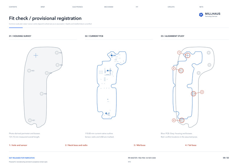
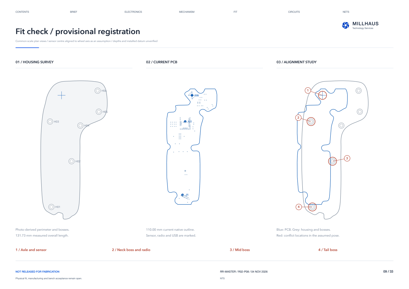
Fit comparison: Original housing and current PCB at the same scale. The alignment is provisional; axle and boss conflicts are marked.
-
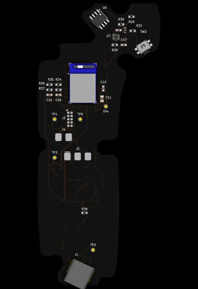
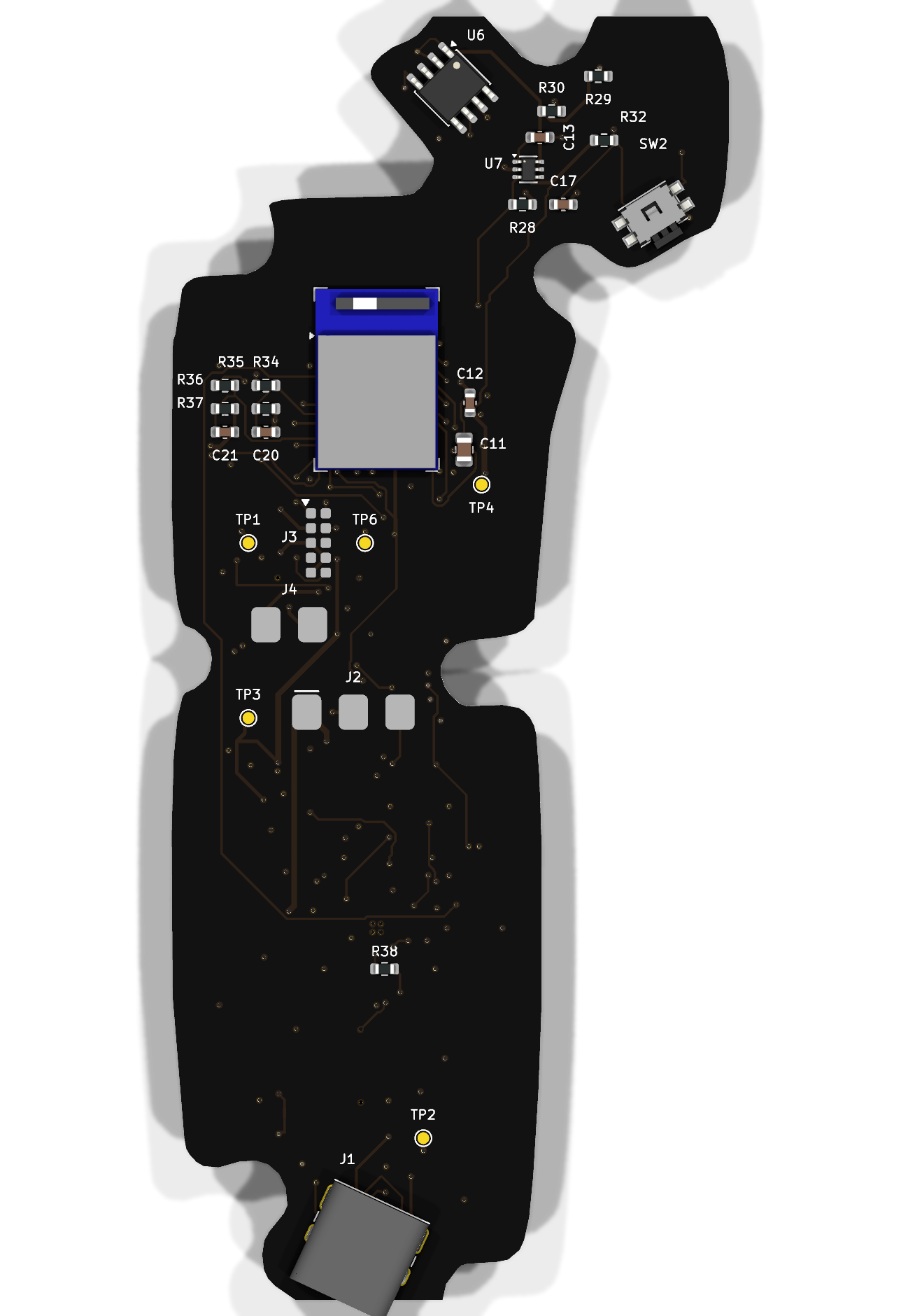
PCB front: Current 110 mm board, with the revised USB routing and tscircuit-assisted R1/R2 placement.
-
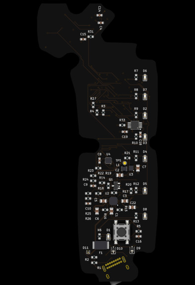
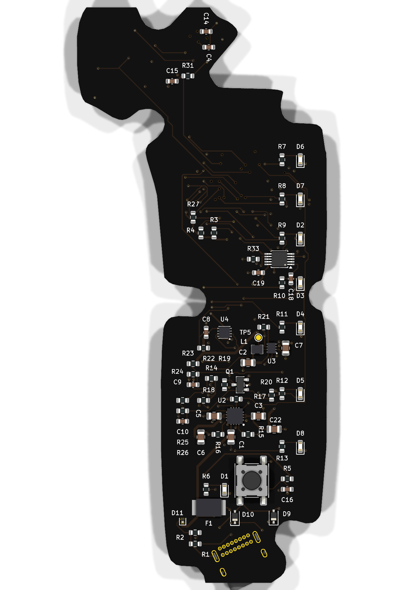
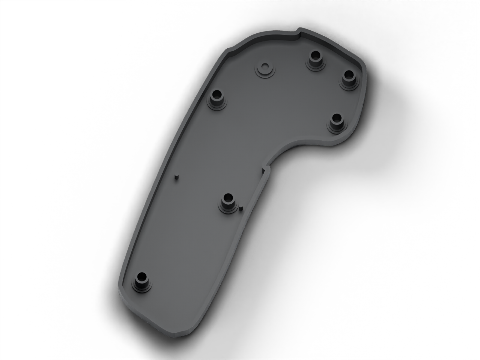
- PCB back: The other side of the current board. Digital checks are clear; physical fit and powered operation are still unverified.
-
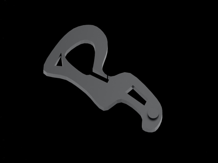
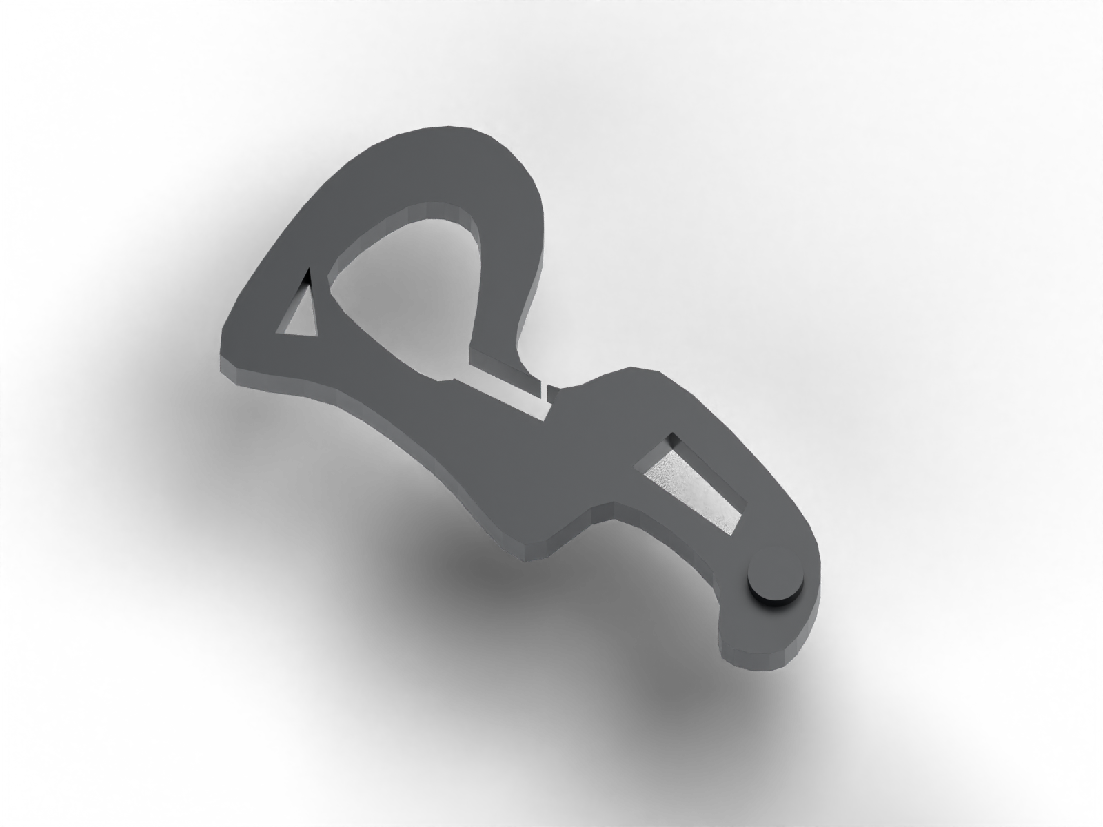
Trigger / jig: Photo-derived reconstruction of the detached trigger piece. Its installed position is still unconfirmed.
-
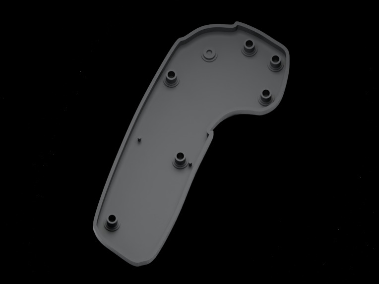
-
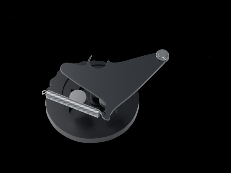
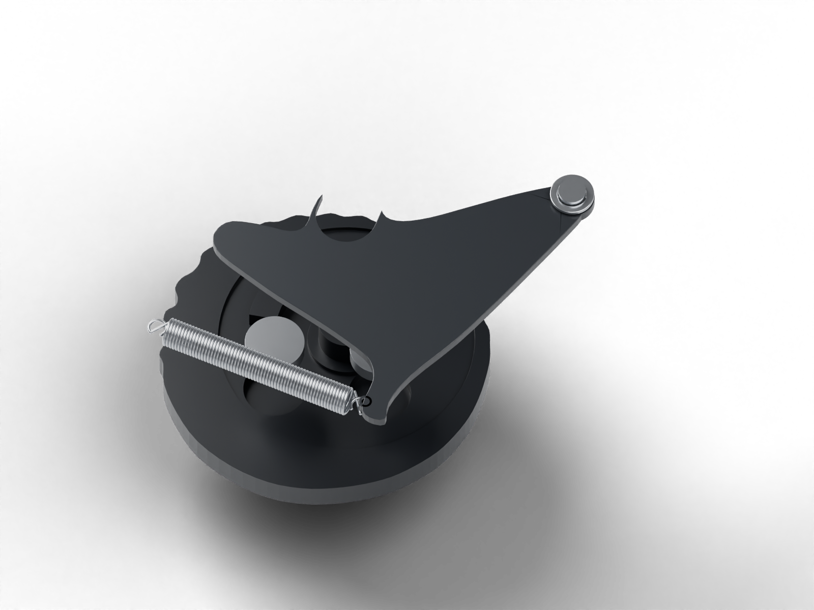
Wheel and return mechanism: Reconstructed from the new photos: one extension spring, a triangular lever, and the wheel’s crescent guide.
-
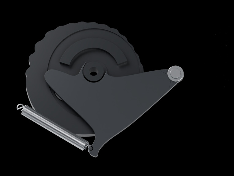
Wheel and return mechanism: Reconstructed from the new photos: one extension spring, a triangular lever, and the wheel’s crescent guide.
-
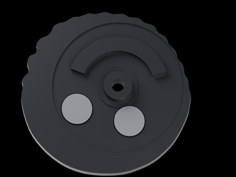
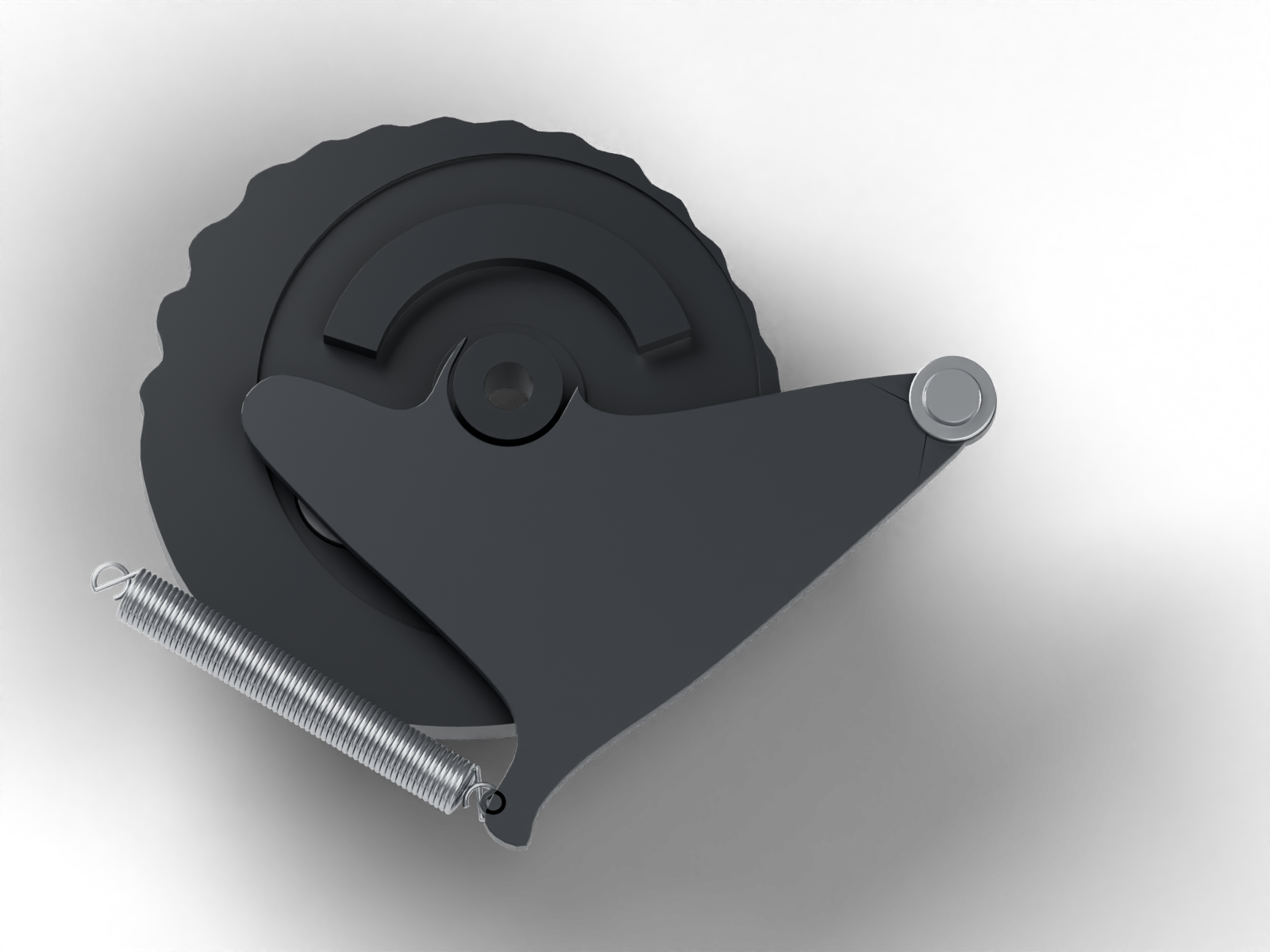
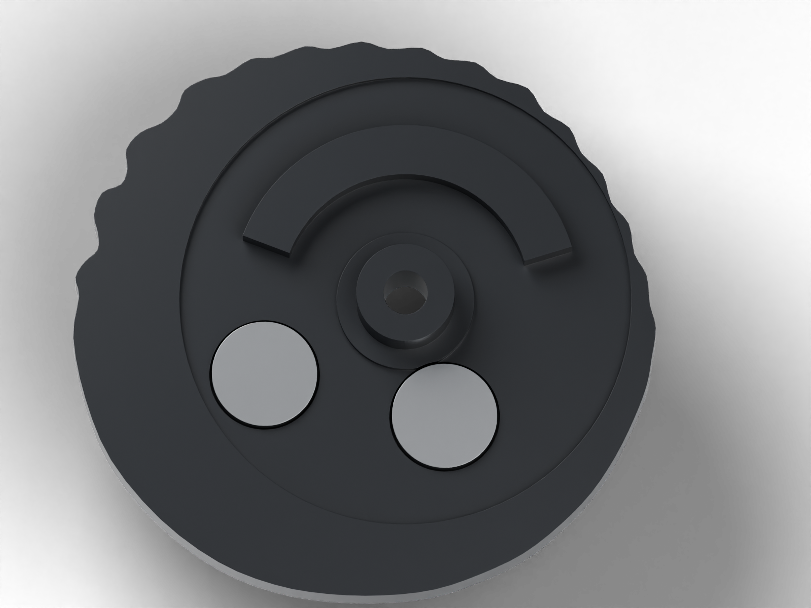
Wheel: The 33.78 mm wheel with its centre hub, crescent guide, and two insert pockets.
-
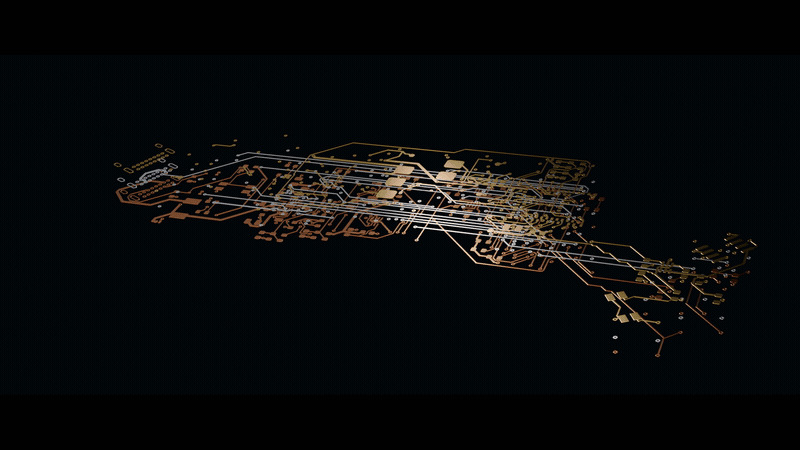 GIF
Same remote; Better Models
Earlier this year, I used Codex to reverse-engineer a Boosted Boards electric-skateboard remote. Part 1 explored the electronics. Part 2 got into the enclosure, wheel, trigger, and spring mechanism.
I got much further than I expected. I also ended up with a graveyard of scripts, CAD exports, half-finished experiments, and things that looked more convincing than they were.
A few months later, the models had improved. So I came back to the same remote, took it apart again, and picked up where I’d left off.
Why revisit now?
AI-assisted hardware design is moving fast. BenchCAD 2.0 now evaluates parts, assemblies, and circuit connectivity, and OpenAI and Anthropic are training on this specifically. I wanted to see what those improvements felt like on a problem I already knew was messy.
The remote was perfect for that. It’s small, but there’s a lot packed into it: a wireless controller, battery and charging circuit, an oddly-shaped PCB, a throttle wheel, magnets, a trigger, and a spring-loaded mechanism. Everything has to fit together, and every time I opened it up I found another detail worth looking at.
BenchCAD 2.0 · OpenAI: Accelerating engineering for the physical world
Revisiting the electrical design
The electronics now live in one native KiCad project. Codex helped reconcile component pinouts and footprints, revise the power and charging circuits, and route the four-layer board.
The current board has 94 footprints and 93 nets. Its saved checks report zero ERC errors or warnings, DRC violations, unconnected items, and schematic-parity findings.
I measured the original PCB at 110 mm long, so we brought the new board into line with that measurement. I also tried tscircuit for component placement and a local USB routing update. The checks stayed clear after the changes.
There was a lot of steering along the way. Codex handled much of the detailed CAD work while I reviewed the outputs and caught things like the power-switch actuation, the trigger-switch orientation, and the battery choice.
Design legibility
PCB design gets complicated fast. I wanted to be able to pick a part of the circuit and actually see where it goes.
So we made a colour-coded net register and filtered board views grouped by function. I can choose a signal, see its endpoints, and follow its path through the board.
The engineering reference brings those views together with the schematics, PCB drawings, mechanical survey, and fit comparison. It’s become my map for navigating the project.
Back inside the remote
The first mechanical pass gave me a starting point, but the new photos showed where it had gone astray. I’d modelled an opposed-spring cassette; the original has one extension spring, a triangular lever, and a crescent-shaped guide on the wheel.
So we went back through the enclosure, screw bosses, mounting points, wheel, jig, spring, and their placements. I measured the enclosure at 131.73 mm long and the wheel at 33.78 mm across. Those measurements gave us a better foundation for rebuilding the parts.
The updated Blender and FreeCAD models bring the current board and the reconstructed enclosure into the same review. One of my favourite additions is a side-by-side fit page: housing, PCB, and alignment at the same scale, with the problem areas called out. Turns out the board and shell still have some disagreements. Good to know before sending anything off to be made.
Bring the circuits to life
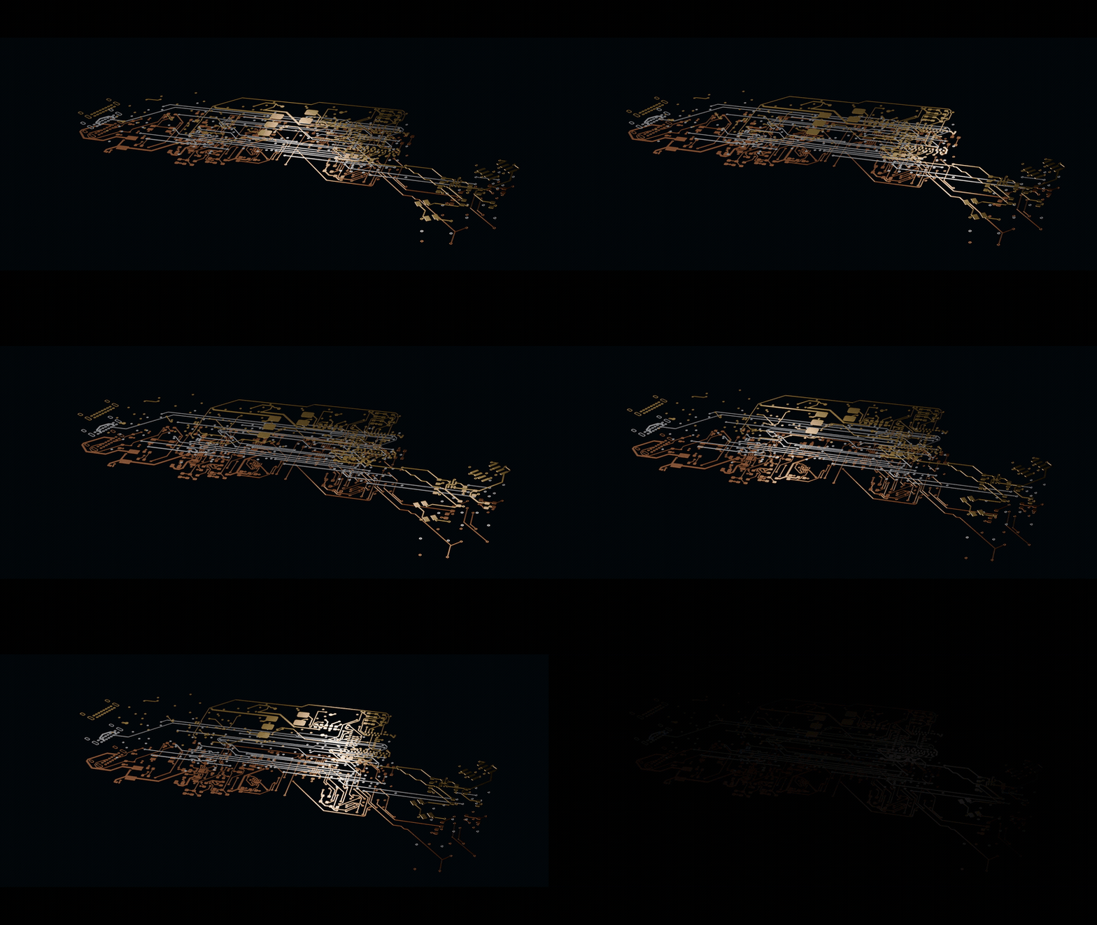
I also made a 32-second Blender study of the copper artwork: gold, silver, and bronze finishes, slower camera movement, controlled reflections, and a gradual layer reveal.
It uses an earlier copper export, and the finishes and exploded spacing are artistic choices. I just wanted to see the circuit in a different way—and it turns out a PCB makes a pretty good subject for a short film.
Transferred learnings
The biggest improvement I noticed was the speed & quality of the feedback loop. PCB design is super complex, and requires a lot of back and forth, and trade-offs. Make a bounded change, inspect the native result, run the relevant checks, preserve the evidence, and keep going.
The agent could move between research, code, KiCad, FreeCAD, Blender, and documentation while I kept coming back to the physical remote: measuring it, taking photos, and pointing out what looked wrong. Each pass gave us something more concrete to work with.
This was not a one-prompt product. There was plenty of back-and-forth, and that’s what made it interesting.
Where it stands
The board is routed and digitally checked. The enclosure and mechanism are much closer to the original, and I have a clearer picture of what still needs work.
The next step is a physical prototype: fit the board, check the controls and clearances, and bring it up on the bench. After spending this much time looking at it on a screen, I’m looking forward to holding the thing.

Log in or sign up for Devpost to join the conversation.