In Part 1, "From Prompt to Printed Circuit Board", I outlined how I reverse engineered the PCB design of the Boosted Boards electric skateboard remote with GPT 5.4 Codex.
In that write-up, I showed how it’s now possible to use a coding agent to generate an end-to-end PCB design using the open-source electrical engineering software KiCAD (and a bit of thumb grease).
Prior to the start of this project, I’d never used KiCAD or any other software for circuit design (I just fried boards the old fashion way). Same for mechanical CAD, with a minor exception for a few hours spent learning the basics in Fusion360 and Blender.
In Part 2, I extend the electrical engineering and design work from Part 1 to include the mechanical enclosure and assemblies for the Boosted Board remote as well.
This time, I asked
*"What if I gave Codex the tools a mechanical engineer or designer actually uses?"
This time, my toolkit included GPT 5.4 Codex, Trellis 2 (image-to-3D model), Python, build123D (parametric CAD), Trellis 2 and Blender.
As with the circuit board design work, I found that giving a coding agent (Codex) the right tools (in this case build123d and Blender) represents a major advancement for digital fabrication. Very few people seem to have realized that this entirely possible today.
Agentic Mechanical Design
Real hardware products involve a lot more than just a PCB. Besides electrical, the hardware development process leans heavily on mechanical engineering and design. Similar to how PCBs start as software, the mechanism of every gizmo or gadget is designed with pixels first.
So, if I wanted to finish the project of reverse engineering the Boosted Boards remote, I figured I needed to do the mechanical design work as well (were pretending the firmware and actual deck, battery, and drive train don’t exist for now.)
Parametric Design vs WIMPy CAD
Most CAD tools treat parameters as inputs to manually operated geometry, rather than treating design as a system of relationships, constraints, and intent.
Parametric design is the process of using parameters to define the keys and values of a modelled object. While parametric design has been around for a while, traditionally it’s been used in more of a UI-centric way. Designers would typically be working in their CAD software’s 3D workspace within a WIMP framework (windows, icons, menus, pointer). specify a measurement or a value and then maybe manually reposition apart or scale it or rotate it, etc.
Export & Import
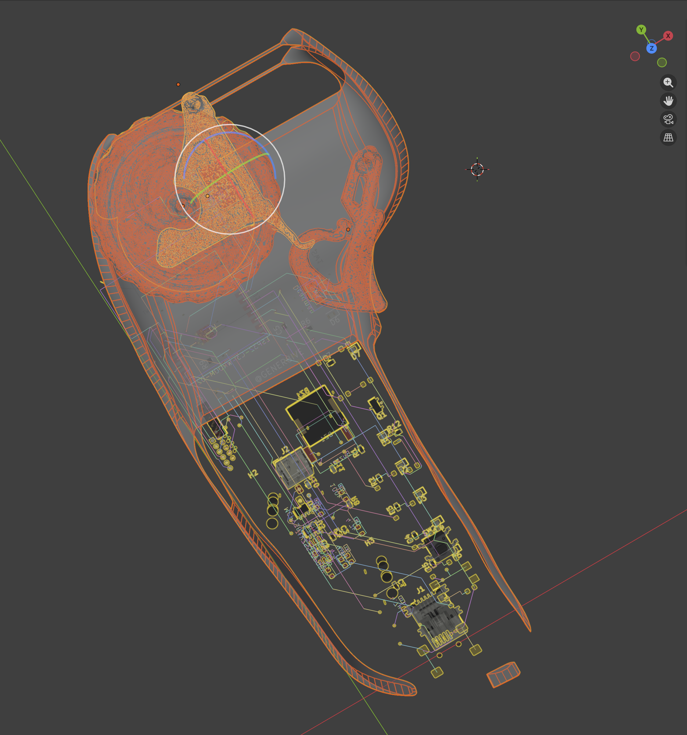
After exporting the routed PCB layout from KiCAD and generating the mechanical assemblies via Build123D, I imported the 3D CAD models into Blender and manually resized, rotated, and aligned the components in 3D space.
Ergonomic Design
Besides a forest axe and a football, the Boosted Boards remote is one of the best designed pieces of hardware I've ever held in my hand.
Because steering on a longboard is done entirely through balance, the remote is purely for acceleration & braking.
So, given how far I got with Codex on reverse engineering the electrical design side of things, I figured the next step would be to see if it could do mechanical design as well.
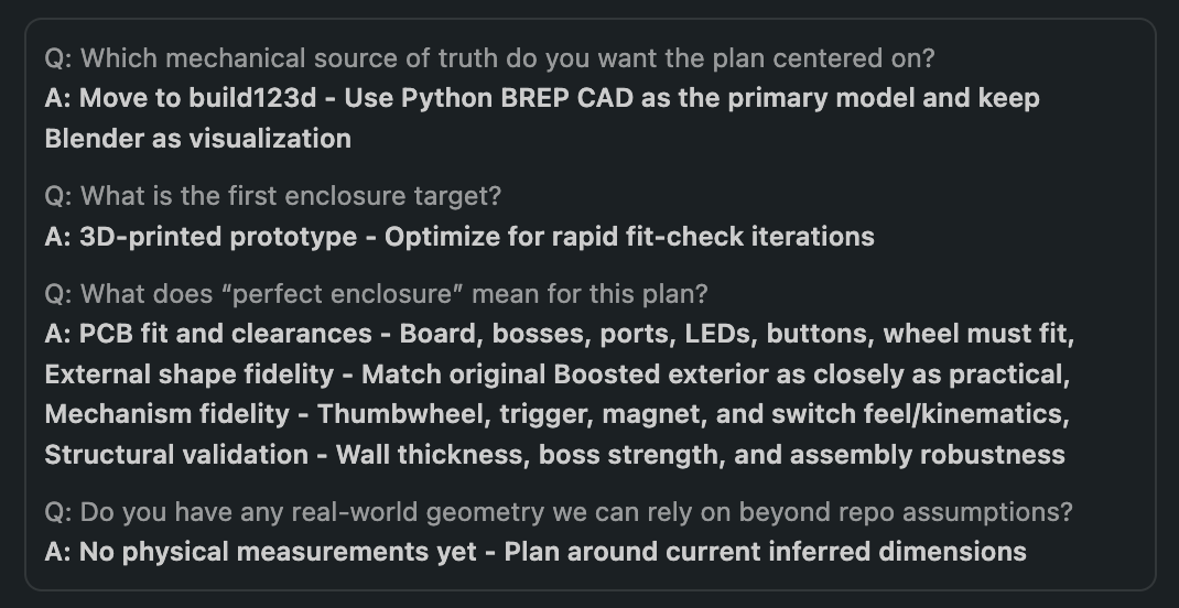
With some pictures of the remotes shell, I asked Codex to extract the shape for the form factor, and then let it do its thing. After asking me to confirm which CAD tool to use, what I meant by "perfect enclosure", and asking politely if I could give it some measurements....it proceeded to build out a first pass on the 3d model for the remote enclosure.
Confirming how and what to build:
In the same remote_params.json file where we defined our PCB's electrical requirements, Codex added mechanical requirements with which to generate the enclosure.
"mechanical": {
    "outer_height_mm": 136.0,
    "outer_width_top_mm": 54.0,
    "outer_width_grip_mm": 36.0,
    "outer_thickness_mm": 20.0,
    "wall_thickness_mm": 2.2,
    "split_gap_mm": 0.25,
    "top_bulb_height_mm": 44.0,
    "grip_height_mm": 92.0,
    "pcb_height_mm": 111.0,
    "pcb_width_top_mm": 40.0,
    "pcb_width_grip_mm": 28.0,
    "pcb_bottom_radius_mm": 8.0,
    "thumbwheel_opening_diameter_mm": 24.0,
    "thumbwheel_center_z_from_top_mm": 24.0,
    "thumbwheel_center_x_mm": 11.0,
    "thumbwheel_diameter_mm": 31.0,
    "thumbwheel_width_mm": 14.0,
    "usb_port_width_mm": 8.6,
    "usb_port_height_mm": 4.2,
    "led_window_diameter_mm": 2.0,
    "status_led_pitch_mm": 4.6,
    "bar_led_pitch_mm": 6.0,
    "button_hole_diameter_mm": 5.0,
    "power_button_center_x_mm": 8.0,
    "power_button_center_z_from_top_mm": 117.0,
    "pcb_shell_center_x_mm": 99.0

}
With a bit of tweaking, I was able to get Codex to generate a usable enclosure based on essentially just a picture of the original remote. I repeated this for a few of the other key mechanical assemblies - the throttle wheel, trigger, and spring loaded jig. It took the photo of the original remote, extracted the shape via a silhouette filter, and then wrote a Python script to generate the enclosure:
I tried a variety of different approaches to recreate parts, eventually settling on an image-to-3d model called Trellis-2
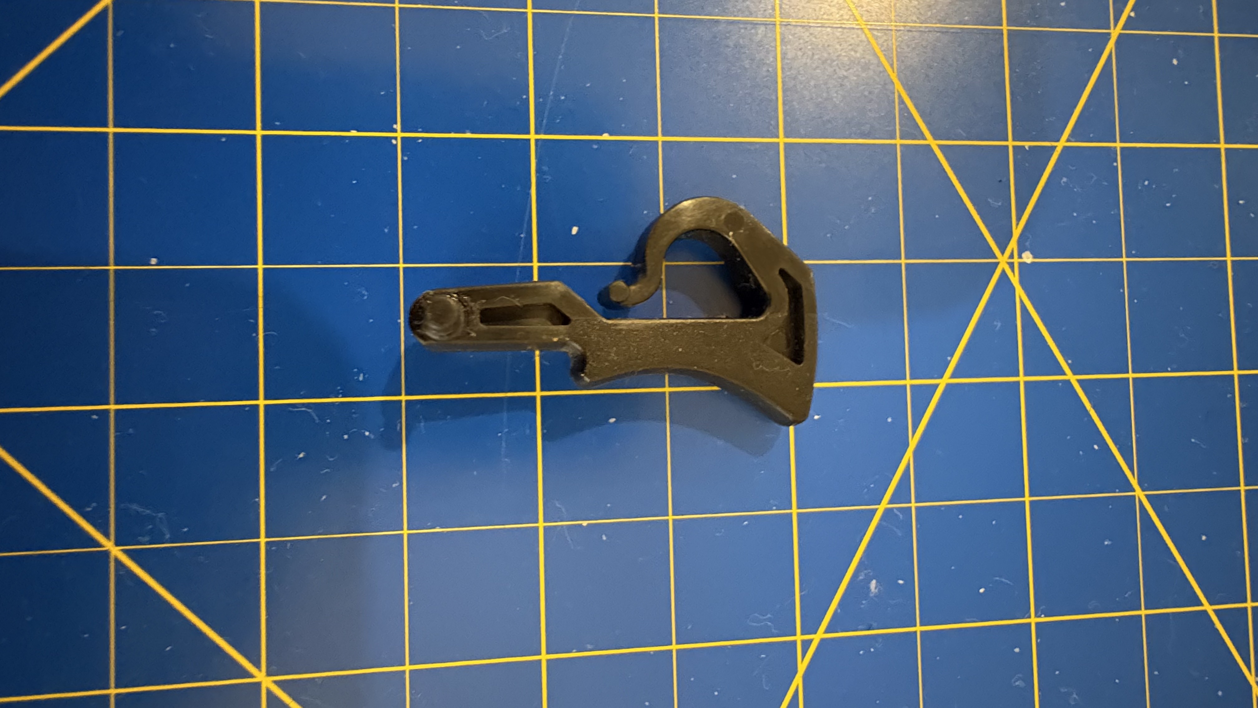
I eventually figured out that I could take a photo of an existing part, remove the background (with MacOS), and then use the shape's outline as a 2D proxy from which to generate a 3D model of the part. This seemed to work better than starting from raw geometric primitives like circles, cylinders, etc.
Step 1: Take a photo of the part you want to replicate.
![[IMG_0389.jpeg]]
Step 2: Convert the photo with an image-to-3D model. The Trellis 2 model from Microsoft was super helpful in converting 2D images into high fidelity 3D models for complex geometries where parametric approaches (Codex + build123d) fell short. When I tried earlier image-to-3D models back in 2024, it was clear they were going to be useful one day soon. I think that day has arrived.
Step 3: Download and import the 3D model into your CAD tool (Blender below)
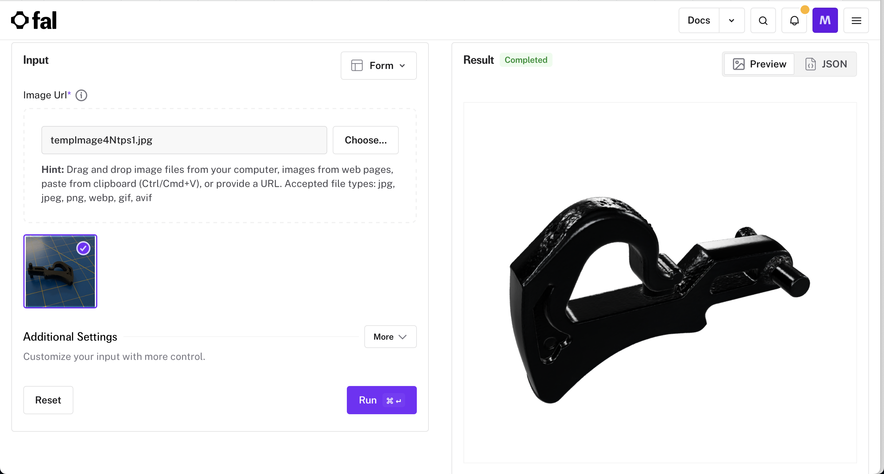
Step 4: Repeat steps 1-3 for all mechanical assemblies
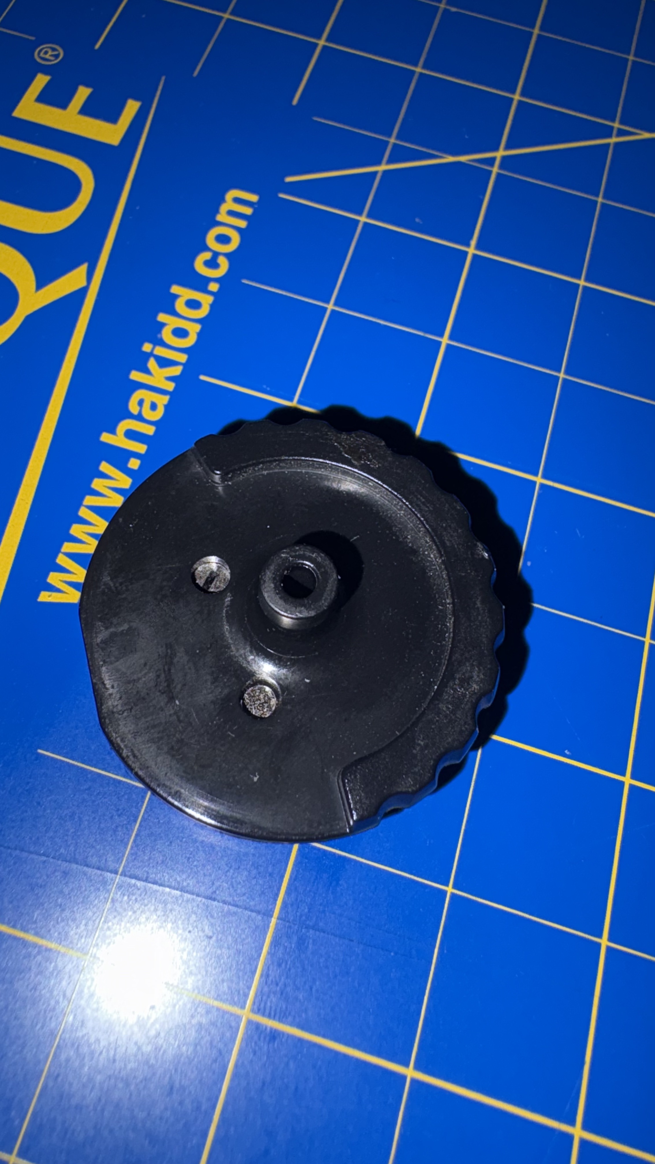
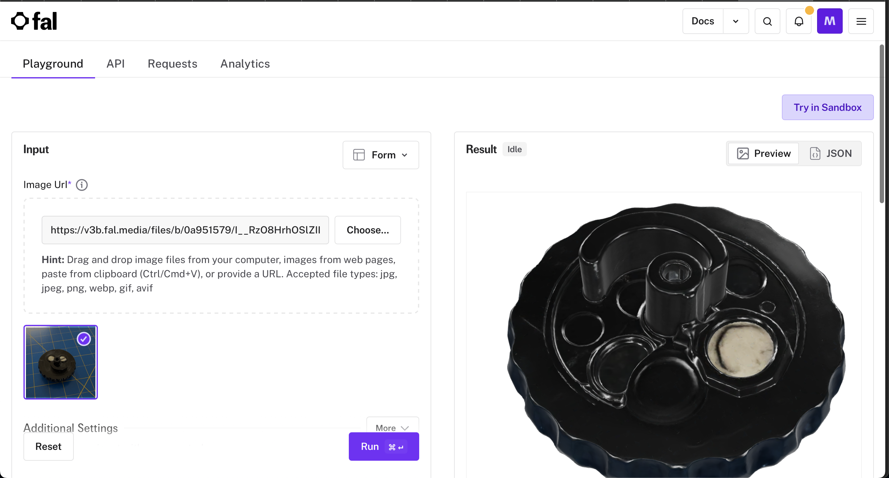
Step 5: Scale, align, rotate, and assemble the parts in a 3D workspace (Blender)
![[Pasted image 20260405230853.png]]
Step 6: Refer back to the reference design and enclosure parameters for ground truth.
Boosted Boards Spring Loaded Throttle Mechanism
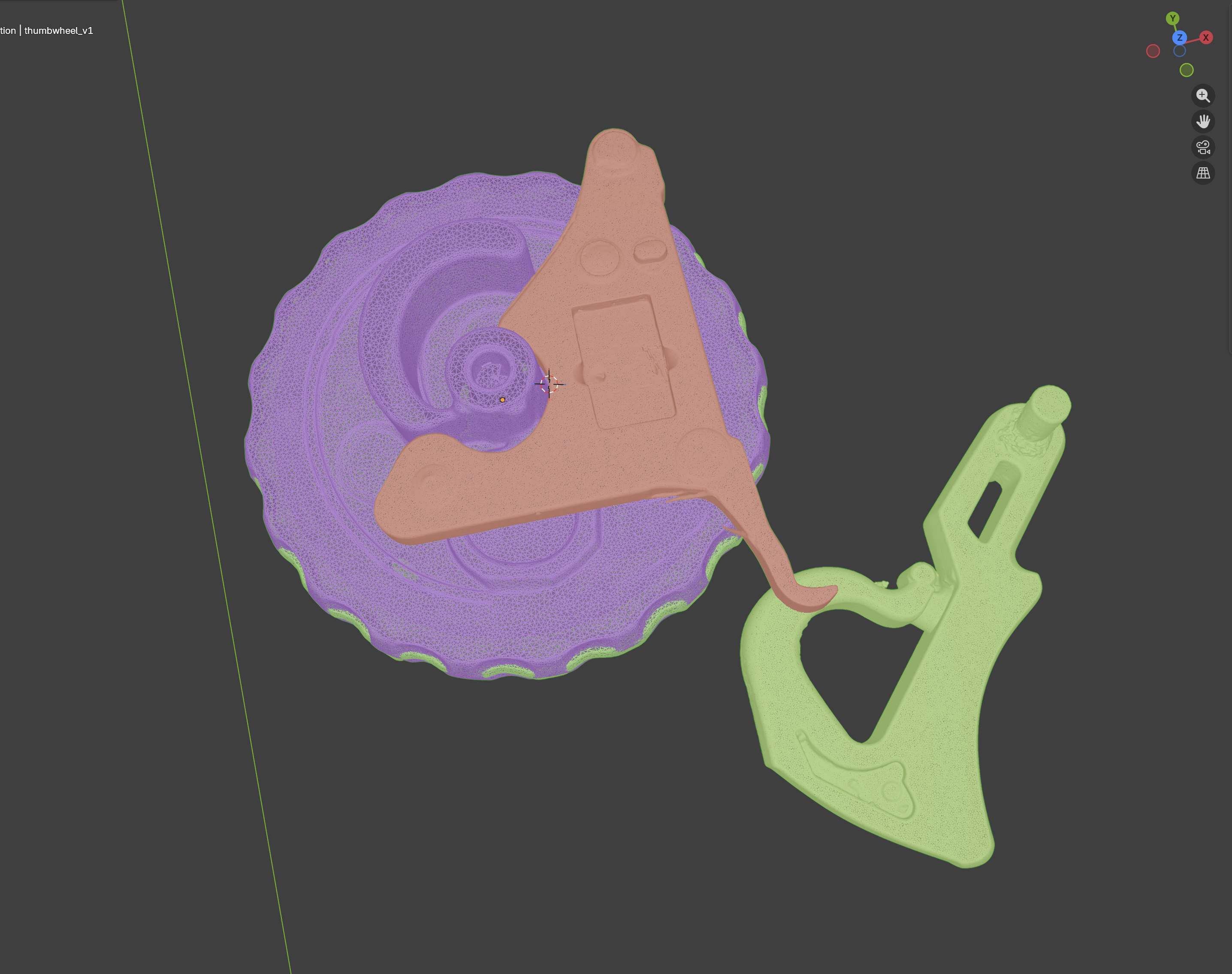
![[Pasted image 20260406115803.png]]
Comparing to the Original Enclosure ![[Pasted image 20260406163330.png]]
def import_proxy_body():

log(f"enclosure: importing proxy {PROXY_GLB}")
bpy.ops.import_scene.gltf(filepath=str(PROXY_GLB))
imported = [obj for obj in bpy.context.selected_objects if obj.type == "MESH"]
if not imported:
    imported = [obj for obj in bpy.context.scene.objects if obj.type == "MESH"]
if not imported:
    raise RuntimeError(f"No mesh objects imported from {PROXY_GLB}")
if len(imported) == 1:
    body = imported[0]
    select_only([body])
else:
    select_only(imported)
    bpy.ops.object.join()
    body = bpy.context.active_object
log(f"enclosure: proxy meshes={len(imported)}")
body.name = "outer_body"
fit_proxy_to_target(body)
log("enclosure: proxy fitted")
decimate = body.modifiers.new("proxy_decimate", type="DECIMATE")
decimate.ratio = 0.08
decimate.use_collapse_triangulate = True
bpy.ops.object.modifier_apply(modifier=decimate.name)
log("enclosure: proxy decimated")
smooth = body.modifiers.new("proxy_smooth", type="SMOOTH")
smooth.factor = 1.2
smooth.iterations = 8
bpy.ops.object.modifier_apply(modifier=smooth.name)
bpy.ops.object.shade_smooth()
log("enclosure: proxy smoothed")
return body
Prompt Snippets
![[Pasted image 20260404145253.png]]
![[Screenshot 2026-04-05 at 2.41.36 AM.png]]
Project Screenshots
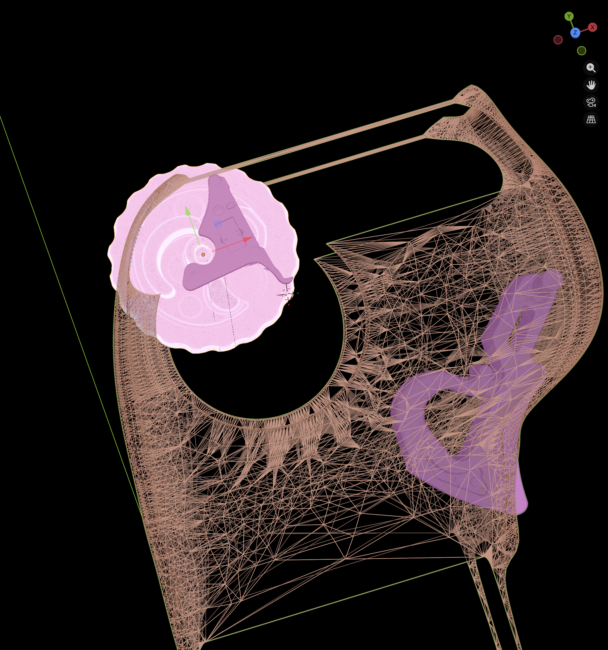
Wireframe in FreeCAD ![[Pasted image 20260404210950.png]]
Modelling in Blender ![[Pasted image 20260405021810.png]]

Log in or sign up for Devpost to join the conversation.