Inspiration
. Project Story
Imagine a disaster situation such as a flood, earthquake, landslide, cyclone, or forest emergency.
The first thing that often becomes a problem is communication.
Mobile towers may be damaged, electricity may be unavailable, and internet connectivity may completely disappear. A person trapped in a remote area may have a phone, but the phone cannot communicate with the rescue team because there is no cellular network.
This creates a critical question:
How can a victim send an emergency message when there is no mobile network or internet?
Our project, ResQMesh, is designed to solve this problem.
It is a low-cost, deployable emergency communication network based on ESP32 and LoRa technology. Instead of depending on mobile towers or the internet, the system creates its own communication path using multiple LoRa relay nodes.
A victim presses an SOS button. The victim node collects the victim's location using GPS and creates an emergency packet. This packet is transmitted using LoRa.
If the rescue station is not directly reachable, the packet is passed from one relay node to another:
Victim → Relay → Relay → Relay → Base Station
This is the basic idea of our LoRa mesh communication network.
- What is ResQMesh?
ResQMesh stands for a deployable emergency communication network that can provide communication between victims and rescue operators in areas where normal communication infrastructure is unavailable.
The system consists mainly of:
Victim Node LoRa Relay Nodes Base Station Rescue Operator Dashboard Backend System Database Mobile/Web Application
The hardware communication layer uses:
ESP32 SX1278 LoRa module GPS SOS button Relay nodes Base station
The software layer uses:
Spring Boot REST APIs Microservices MySQL Web/mobile frontend
- The Main Problem
During normal conditions, communication works like this:
Victim ↓ Mobile Phone ↓ Mobile Tower ↓ Internet ↓ Rescue Centre
But during a disaster:
Victim ↓ ❌ Mobile Tower Damaged ↓ ❌ Internet Unavailable ↓ ❌ Communication Lost
So even if the victim knows that help is available, they may not be able to communicate their location.
ResQMesh removes the dependency on the mobile tower.
Instead:
Victim ↓ LoRa ↓ Relay Node ↓ LoRa ↓ Relay Node ↓ LoRa ↓ Base Station ↓ Rescue Team
- Why LoRa?
LoRa means Long Range.
LoRa is useful for this project because it can communicate over relatively long distances while consuming low power.
The important advantage is:
LoRa communication does not require a mobile tower or Wi-Fi router between the communicating nodes.
For example, suppose a victim is located deep inside a disaster zone.
The victim node may not have a direct LoRa connection to the rescue station.
Instead, we can deploy relay nodes throughout the area.
            Relay 1
               ↓
Victim → Relay 2 → Relay 3 → Base Station ↑ Relay 4
The relay nodes help extend the communication coverage.
- Complete System Architecture
The overall architecture can be understood in four layers.
┌───────────────────────────────────────────────┐ │ VICTIM LAYER │ │ │ │ ESP32 + GPS + LoRa + SOS Button │ └──────────────────────┬────────────────────────┘ │ │ LoRa ↓ ┌───────────────────────────────────────────────┐ │ MESH LAYER │ │ │ │ Relay Node 1 ←→ Relay Node 2 ←→ Relay Node 3 │ │ │ │ ESP32 + SX1278 LoRa │ └──────────────────────┬────────────────────────┘ │ │ LoRa ↓ ┌───────────────────────────────────────────────┐ │ BASE STATION │ │ │ │ ESP32 + SX1278 LoRa │ └──────────────────────┬────────────────────────┘ │ │ Serial / API ↓ ┌───────────────────────────────────────────────┐ │ SOFTWARE LAYER │ │ │ │ Spring Boot Backend │ │ ↓ │ │ REST APIs / Microservices │ │ ↓ │ │ MySQL Database │ │ ↓ │ │ Rescue Operator Dashboard / Mobile App │ └───────────────────────────────────────────────┘
- Victim Node
The Victim Node is the device carried or provided to a person inside the disaster area.
It contains:
ESP32 + SX1278 LoRa + GPS + SOS Button Its job is simple:
When the victim presses the SOS button:
ESP32 detects the button press. GPS obtains latitude and longitude. ESP32 creates an emergency packet. Packet is transmitted through LoRa. Nearby relay nodes receive it.
For example:
SOS Button Pressed ↓ GPS Location Obtained ↓ Emergency Packet Created ↓ LoRa Transmission
- Emergency Packet
The victim node does not simply send "HELP".
It creates a structured packet.
For example:
Packet ID: SOS1025 Source ID: VICTIM01 Latitude: 11.0168 Longitude: 76.9558 Message: EMERGENCY Hop Count: 5
The important fields are:
Packet ID
A unique ID for the emergency message.
Example:
SOS1025
This is important because relay nodes may receive the same packet multiple times.
Source ID
Identifies the victim/device that originally generated the packet.
Example:
VICTIM01 Latitude and Longitude
These represent the victim's location.
Example:
Latitude: 11.0168 Longitude: 76.9558
The rescue operator can use these coordinates to understand where the victim is located.
Message
Contains the emergency information.
Example:
SOS
or
HELP_REQUIRED Hop Count
This represents how many relay transmissions the packet can still make.
For example:
Hop Count = 5
After one relay:
Hop Count = 4
Then:
3 2 1 0
When it reaches zero, the packet should no longer be forwarded.
This prevents packets from circulating indefinitely.
- Relay Nodes
Relay nodes are the heart of the mesh communication system.
A relay node contains:
ESP32 + SX1278 LoRa
Its main job is:
Receive → Check → Forward
Suppose:
Victim ↓ Relay 1 ↓ Relay 2 ↓ Relay 3 ↓ Base Station
Relay 1 receives the packet.
It checks:
Have I already received this Packet ID?
If yes:
Discard packet
If no:
Store Packet ID Decrease Hop Count Forward packet
This is how the system avoids unnecessary duplicate transmissions.
- Flooding Algorithm
Our mesh communication uses a flooding-based forwarding approach.
The basic logic is:
Receive Packet ↓ Check Packet ID ↓ Already received? / \ YES NO ↓ ↓ Discard Check Hop Count ↓ Hop Count > 0? / \ NO YES ↓ ↓ Discard Decrease Hop ↓ Forward
For example:
Victim Packet ID = SOS100 Hop = 5 ↓ Relay A Hop = 4 ↓ Relay B Hop = 3 ↓ Relay C Hop = 2 ↓ Base Station
- Why Duplicate Detection Is Important
Flooding can cause the same packet to reach a relay from multiple directions.
For example:
         Relay A
        ↙       ↘
Victim → Relay B Relay C ↘ ↙ Relay D ↓ Base Station
Relay D might receive the same:
SOS100
from both Relay B and Relay C.
Without duplicate detection:
SOS100 → forward SOS100 → forward SOS100 → forward SOS100 → forward
This creates unnecessary traffic.
Therefore, every relay maintains a record of previously received Packet IDs.
Received Packet IDs
SOS100 SOS101 SOS102
If SOS100 arrives again:
Already seen → Discard
- Base Station
The Base Station is the gateway between the LoRa network and the software system.
It contains:
ESP32 + SX1278 LoRa
It continuously listens for emergency packets.
When the packet reaches the base station:
LoRa Mesh ↓ Base Station ↓ Serial Communication ↓ Backend
The base station receives information such as:
Victim ID Packet ID Latitude Longitude Message
The backend can then process and store the information.
- Backend
The backend is responsible for managing the information received from the hardware network.
Your project uses Java Spring Boot for the backend.
The backend architecture is organized using microservices.
For example:
API Gateway │ ├── Auth Service ├── User Service ├── Worker Service ├── Team Service ├── Rescue Service └── Relay Service
Each service has a specific responsibility.
This makes the system easier to maintain and expand.
- Database
MySQL is used for storing system information.
The system can store information such as:
Users Workers Rescue Teams Devices SOS Alerts Rescue History Locations Messages
For example, an SOS record could contain:
SOS ID Victim ID Latitude Longitude Message Time Status Assigned Team Rescue Status
- Rescue Operator Dashboard
Once the emergency reaches the backend, the rescue operator can see it on the dashboard.
For example:
┌───────────────────────────────────────┐ │ EMERGENCY ALERT │ ├───────────────────────────────────────┤ │ Victim: VICTIM01 │ │ Location: 11.0168, 76.9558 │ │ Status: PENDING │ │ Priority: SOS │ │ │ │ [ VIEW LOCATION ] [ ACCEPT SOS ] │ └───────────────────────────────────────┘
The rescue team can then take action.
- Rescue Team Workflow
The complete workflow becomes:
Victim presses SOS ↓ GPS gets location ↓ Victim Node creates packet ↓ LoRa transmission ↓ Relay Nodes forward packet ↓ Base Station receives packet ↓ Backend receives information ↓ Database stores SOS ↓ Rescue Dashboard displays alert ↓ Rescue Team accepts SOS ↓ Team goes to victim location ↓ Rescue completed ↓ SOS status updated
- What Happens When There Is No Direct Connection?
This is one of the most important parts of the project.
Suppose:
Victim -------------------------- Base Station ❌ Direct connection
The victim cannot reach the base station.
So relay nodes are deployed:
Victim │ ↓ Relay 1 │ ↓ Relay 2 │ ↓ Relay 3 │ ↓ Base Station
Now the message can travel through multiple hops.
This is why it is called a mesh-based communication network.
- What Happens if One Relay Fails?
This is another important advantage.
Suppose:
Victim ↓ Relay 1 ↓ Relay 2 ↓ Relay 3 ↓ Base Station
Relay 2 fails.
If there is another available path:
         Relay 4
        ↗       ↘
Victim → Relay 1 Relay 3 ↓ Base Station
the packet can potentially reach the base station through another path.
The exact behavior depends on relay placement and the flooding/forwarding implementation.
So the system is designed to be more resilient than a single direct communication link.
- Why This Is Useful During Disasters
The project is particularly intended for environments where conventional communication infrastructure may be unavailable or unreliable.
Examples include:
Flood Water level rises ↓ Power infrastructure damaged ↓ Mobile communication disrupted ↓ ResQMesh deployed ↓ Victims send SOS Earthquake Buildings collapse ↓ Mobile towers damaged ↓ Victims trapped ↓ SOS button pressed ↓ LoRa relay network ↓ Rescue team receives location Landslide Road blocked ↓ Remote area isolated ↓ No cellular connectivity ↓ Victim sends emergency packet ↓ Relay nodes forward message ↓ Base station receives alert Forest Emergency Remote forest ↓ No cellular coverage ↓ Emergency occurs ↓ LoRa communication ↓ Rescue operator receives alert
- AI Layer
Your project can also include an AI-based danger-zone prediction system as an additional intelligence layer.
The LoRa mesh handles:
Communication
while AI handles:
Prediction / Risk Analysis
These are two different responsibilities.
For example:
Environmental / Historical Data ↓ AI Model ↓ Risk Prediction ↓ ┌─────────┼─────────┐ ↓ ↓ ↓ SAFE WARNING DANGER
The AI should not simply say:
"Temperature is high → disaster."
Instead, multiple factors can be considered together.
For example:
Temperature Rainfall Humidity Wind Water Level Historical Disasters Location Terrain Other environmental factors ↓ AI Model ↓ Risk Probability ↓ Safe / Warning / Danger
So if someone asks:
"If the temperature is high, how can you say there is a disaster? Hot weather does not always mean disaster."
The correct explanation is:
The AI does not make a disaster decision using temperature alone. Temperature is only one feature. The model considers multiple environmental and historical features together and learns patterns associated with previously observed dangerous conditions. Therefore, a high temperature by itself does not automatically mean a disaster.
- AI + LoRa Integration
The complete intelligent system can therefore look like:
            ENVIRONMENTAL DATA
                   │
    ┌──────────────┼──────────────┐
    ↓              ↓              ↓
Temperature Rainfall Water Level │ │ │ └──────────────┼──────────────┘ ↓ AI MODEL ↓ Risk Probability ↓ Safe / Warning / Danger │ ↓ Risk Monitoring UI
    ┌─────────────────────────┐
    │    LoRa Mesh Network    │
    │                         │
Victim → Relay → Relay → Base │ └────────────┬────────────┘ ↓ Backend ↓ Rescue Dashboard
The two systems complement each other:
AI predicts risk.
LoRa communicates emergency information when conventional networks are unavailable.
- Mobile Application
The system can also provide a mobile application for users.
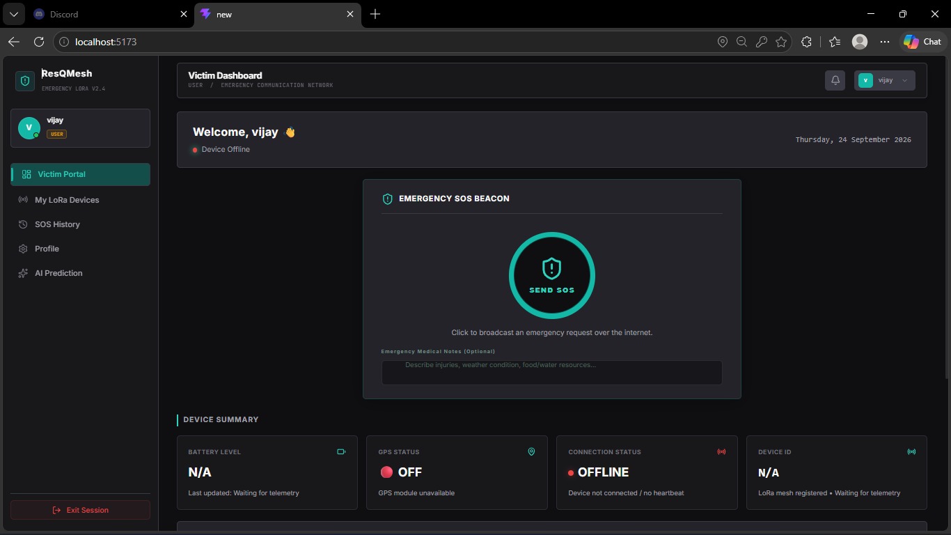
The mobile application can allow users to:
Login View their profile View registered devices Trigger/view SOS information View SOS history Track emergency status Receive relevant notifications
The mobile application communicates with the Spring Boot backend through REST APIs.
Flutter Mobile App ↓ REST API ↓ API Gateway ↓ Microservices ↓ MySQL
- Complete End-to-End Story
Here is the simplest way to explain the entire project during a presentation:
Imagine a person trapped in a disaster-affected area where there is no mobile network or internet. The person has a ResQMesh victim device. When the person presses the SOS button, the ESP32 obtains the person's GPS location and creates an emergency packet containing the Packet ID, Source ID, latitude, longitude, message and hop count.
The packet is transmitted using LoRa. If the base station is not directly reachable, nearby relay nodes receive and forward the packet. Each relay checks whether the Packet ID has already been processed to prevent duplicate forwarding and decreases the hop count before forwarding it.
The packet eventually reaches the base station, which transfers the emergency information to our Java Spring Boot backend. The backend stores the alert in MySQL and makes it available to the rescue operator dashboard. The rescue team can then view the victim's location, accept the SOS and respond to the emergency.
The system can additionally use AI to analyze environmental and historical data and identify areas with different levels of disaster risk such as Safe, Warning and Danger. Therefore, ResQMesh combines two important capabilities: AI-based risk analysis and independent LoRa-based emergency communication.
- One-Line Explanation
If your evaluator asks:
"What exactly is your project?"
Say:
"ResQMesh is a low-cost, deployable LoRa mesh emergency communication system that allows victims to send location-based SOS messages to rescue teams through multi-hop relay nodes even when cellular and internet connectivity are unavailable."
- The Core Innovation
The key idea of the project is not simply using LoRa.
The important combination is:
            ResQMesh
               │
   ┌───────────┴───────────┐
   │                       │
LoRa Mesh AI Layer │ │ Emergency Risk Communication Prediction │ │ └───────────┬───────────┘ ↓ Intelligent Disaster Response System

Log in or sign up for Devpost to join the conversation.