-
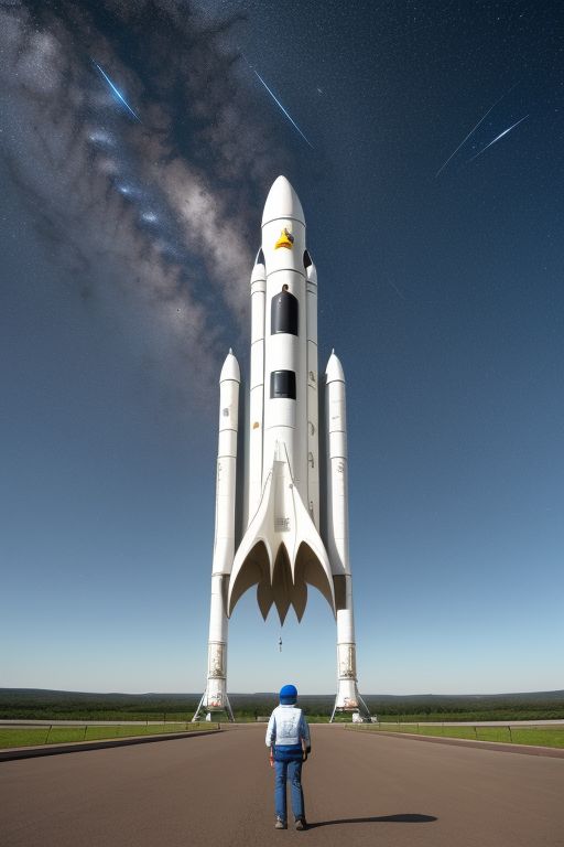
AI
-
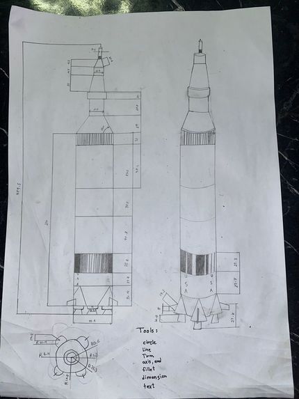
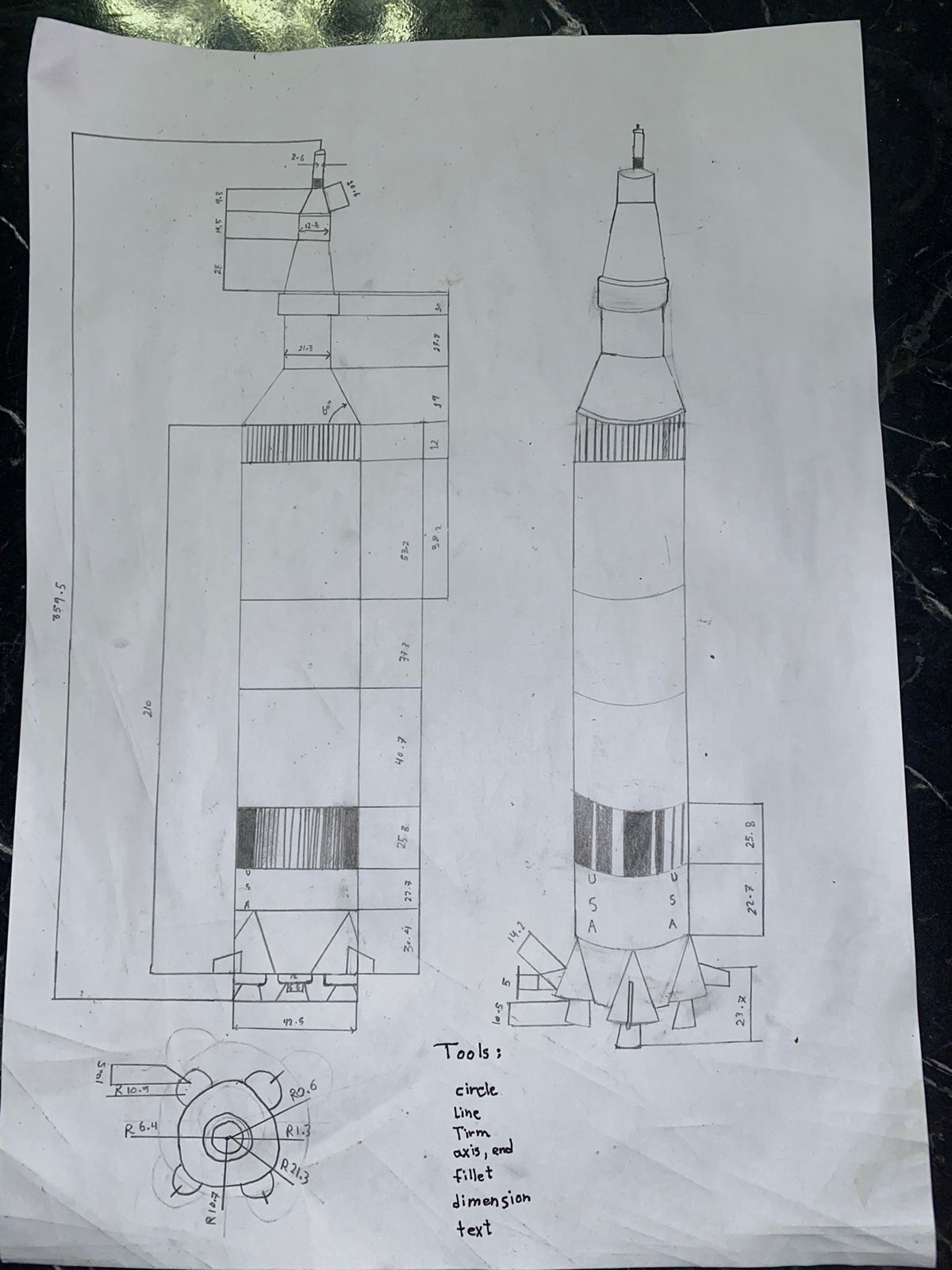
HAND TECH DRAWING PICTURE
-

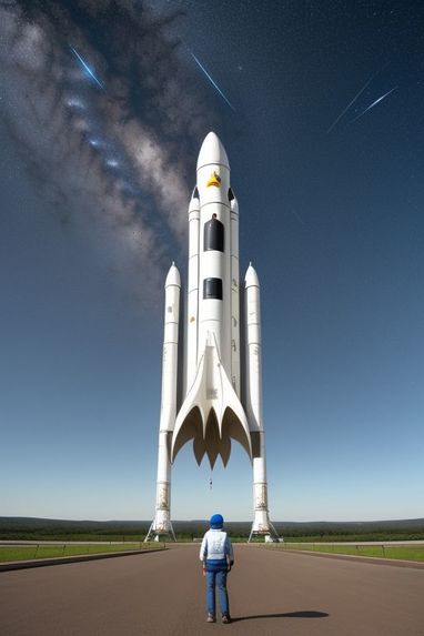
TECHNICAL DRAWING PICTURE
INTRODUCTION
In the pursuit of innovation and technology-driven advancements, AutoCAD has emerged as a fundamental tool that transcends various industries. This report delves into the application of AutoCAD in the intricate process of designing a space rocket, showcasing how this versatile software plays a central role in creating complex and precision-engineered structures.
The mission of this report is to document the journey of crafting a detailed space rocket design using AutoCAD, highlighting the various stages, challenges encountered, and solutions devised. Through a meticulous breakdown of the rocket's key features, dimensions, and specifications, we aim to demonstrate the powerful capabilities of AutoCAD's drawing space.
Designing a space rocket represents a testament to human ingenuity, engineering expertise, and the relentless pursuit of technological excellence. As we explore this project, we invite readers to join us on a voyage through the cosmos, where the fusion of creativity and technology knows no bounds.
AutoCAD has not only served as a tool but as a gateway to a world of possibilities, enabling us to bring our vision of space exploration closer to realization. It has been the canvas upon which our aspirations have taken shape and the compass guiding us toward the stars.
So, let us embark together on this remarkable journey, unraveling the intricacies of space rocket design and recognizing the pivotal role AutoCAD plays in making such extraordinary endeavors achievable.
HOW IT WORKS
AutoCAD is a powerful computer-aided design (CAD) software used by professionals across various industries for creating precise 2D and 3D drawings, schematics, and models. Here's a comprehensive explanation of how AutoCAD works: 1.1. User Interface:
When you launch AutoCAD, you are greeted with a graphical user interface (GUI) that consists of various menus, toolbars, and panels. The ribbon interface at the top provides access to drawing and editing tools organized into tabs and panels.
1.2. Drawing Area:
The central area of the interface is the drawing area where you create your designs. It's a blank canvas where you can draw and manipulate objects.
1.3. Drawing Commands:
AutoCAD offers a wide range of drawing and editing commands accessible through menus, ribbons, or typed in the command line. Common drawing commands include line, circle, rectangle, and polyline.
1.4. Object Creation:
To create objects, users typically select a command and then specify points or parameters in the drawing area. For example, to draw a line, you specify the start and end points.
1.5. Coordinate System:
AutoCAD uses a Cartesian coordinate system to define the position of objects. You can input coordinates directly or use tools like the grid and snap to align objects accurately.
1.6. Layers:
AutoCAD uses layers to organize and manage objects within a drawing. Each layer can have specific properties like color, linetype, and thickness.
1.7. Object Properties:
You can modify object properties such as color, line type, and thickness to customize the appearance of your drawings.
1.8. 3D Modeling:
AutoCAD supports 3D modeling, allowing you to create complex 3D objects and assemblies. You can use commands like extrude, revolve, and sweep to create 3D shapes.
1.9. Precision Tools:
AutoCAD offers a range of precision tools like dimensioning and measuring tools to ensure accuracy in your designs.
1.10. Annotation and Text:
- You can add text, dimensions, and annotations to your drawings to provide information and context.
1.11. Blocks and Symbols:
- AutoCAD allows you to create reusable blocks and symbols for efficiency in drawing repetitive elements.
1.12. File Management:
- AutoCAD supports various file formats for saving and exporting your drawings, including DWG (AutoCAD's native format) and DXF.
1.13. Collaboration and Sharing:
- AutoCAD provides tools for collaboration, including cloud-based storage and sharing options.
1.14. Customization:
- AutoCAD is highly customizable. Users can create custom commands, scripts, and macros using AutoLISP or .NET languages.
1.15. Printing and Plotting:
- AutoCAD supports the printing and plotting of drawings on physical paper or in electronic formats.
1.16. Rendering and Visualization:
- For architectural and design visualization, AutoCAD offers rendering tools to create realistic 3D renderings of your models.
1.17. AutoCAD Add-Ons:
- AutoCAD can be extended with numerous add-ons and plugins to enhance its capabilities for specific industries or tasks.
1.18. Updates and Support:
- AutoCAD is regularly updated by Autodesk to provide bug fixes, new features, and improved performance.
1.19. Training and Learning Resources:
- Users can access a wealth of training materials, tutorials, and online communities to learn and master AutoCAD.
AutoCAD's versatility and extensive feature set make it a go-to choice for professionals in fields such as architecture, engineering, manufacturing, and more. Its ability to handle both 2D and 3D design tasks, along with its customization options, makes it a powerful tool for creating precise technical drawings and complex models.
DRAWING DETAILS (AUTOCAD CODES, DIMENSION ASSUMPTIONS, PARAMETERS, AND DRAWING REFERENCE FIGURES)
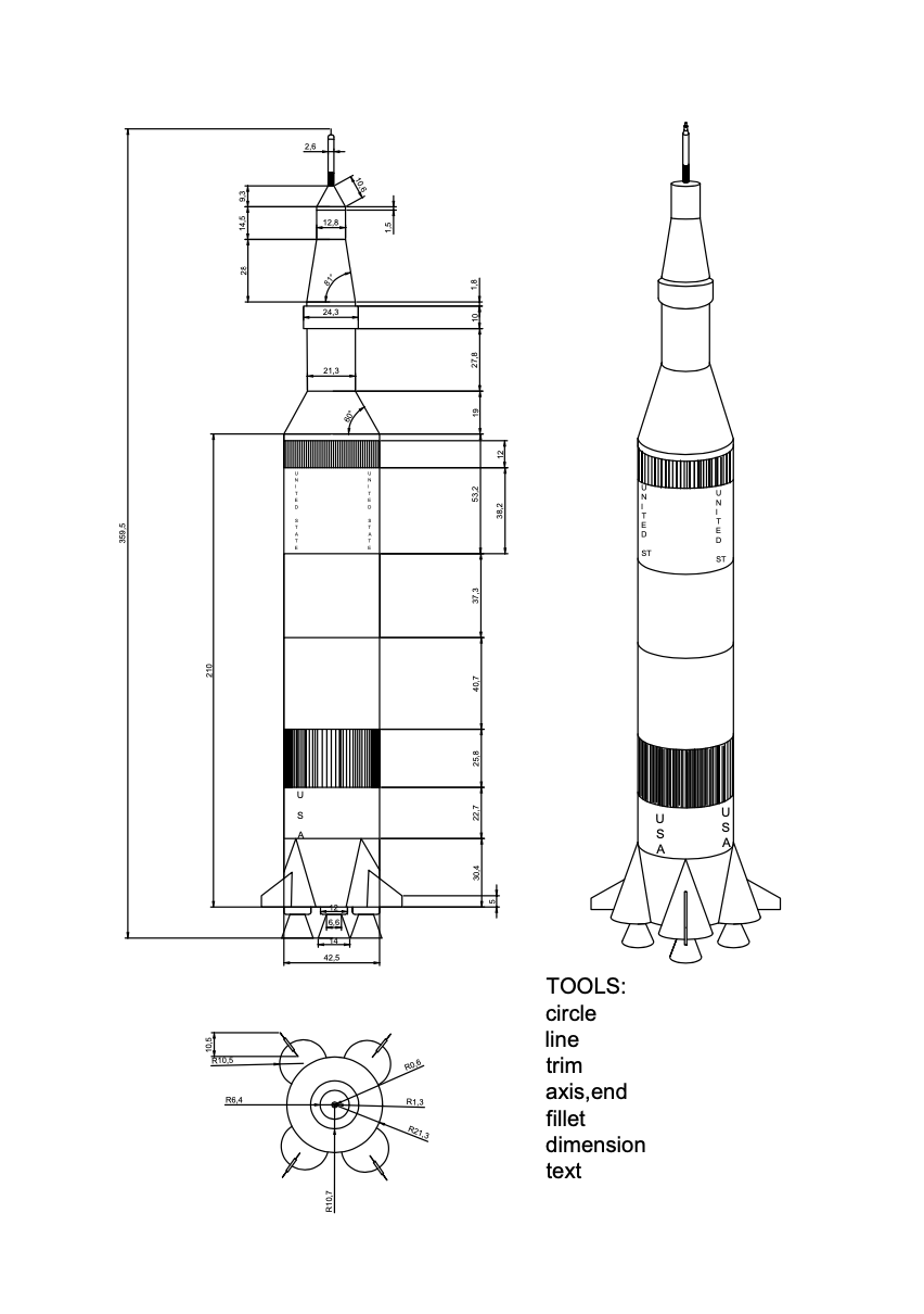
2.1. AutoCAD Commands: AutoCAD offers a wide range of commands for creating, editing, and managing rocket drawings. used commands in rocket drawings: • ‘LINE’ • ‘CIRCLE’ • ‘RECTANGLE’ • ‘POLYLINE’ • ‘INSERT’ • ‘DIMENSION’ • ‘LAYER’ • ‘HATCH’ • ‘EXPORT or ‘PLOT’
2.2.Drawing Steps Detailes
Mohamed Hamid work details: 2.2.1. The steps for [Figuer 2.1] which give as the front view for the Saturn v rocket : in the beginning I drew a rectangle with a length of 210 feet using the Line Tool, then I divided the rectangle from the inside six times with different lengths of 30.4, 22.7, 25.5, 40, 7.37.2, and 53.2. In the first rectangle (30.4), I drew two triangles with different measurements to give the front shape For cylinder shapes, I trimmed the appendages using a trim. At the edge, I took out a line 10 feet long, then I drew a line perpendicular to it with a length of 5 feet, then I connected it in a line inside the triangle with a length of 15.4 feet.To give the shape of rocket wings. At the bottom of the rectangle, I drew three small rectangles 3 feet long and 12 feet wide, then I made their corners curved using fillet. In these rectangles on their bottom side Draw an isosceles trapezoid with a length of 10.5 feet and a width of 14 feet. In the rectangle whose length is 25.8 in the main rectangle, I colored it with lines using array. In the rectangle whose length is 53.2, I took a distance of 38.2, then I drew a rectangle of length 12 and colored it in the same way as the previous rectangle. In the main rectangular surface I have drawn Isosceles trapezoid with length 21.8 And its width is 42.5 Then I drew a rectangle above it Its length is 27.8 and its width is 21.3. Above this rectangle I drew a rectangle with a length of 10 feet and a width of 24.3. Above this rectangle is another rectangle with a width of 21.3 and a length of 1.8. After that, I drew an isosceles trapezoid with a length of 28.3, its lower side is 21.3 and its upper side is 12.8 long. Then I drew a rectangle with a length of 14.5 and a width of 12.8. Then I drew another rectangle with a length of 1.5. Then I drew an isosceles trapezoid with a length of 10.8 on top of it. Then I drew a rectangle with a length of 5, which I colored with lines. Then I drew the last rectangle with a length of 14 and a width of 2.6. I divided the top of the rectangle and made its edges curved.
Mohamed Yusuf work details: 2.2.2. For the top view drawing [ Figuer 2.2] Start drawing a circle by using a cirde tool the diameter of this circle is 42.5 then This circle was divided into four equal parts In corner 45, in each section, I drew a circle with a diameter of 21, and in the middle of these circles was a line with a length of 10.3, and in the middle of it was a rectangle with a length of 5 and a width of 1.5. Then, in the middle of the main circle, I drew 2 other circles with measurements (12.8 and 21.3). Then I trimmed the excess using a Trim
Youness Arab work details: 2.2.3. For the isometric view drawing [Figuer 2.3] based on the measurements in the front View drawin I drew this drawing .First I draw a horizontal circle using (axis,end) to creat a cylinder. To draw the cylinder , I drew a horizontal circle Measures 21.25 , then I drew a line 210 feet long in the middle of it, and at the end of this line I drew another circle The same size as the first circle Then I drew two columns at the edges of the two circles to give it a Cylindrical shape . Then I divided the Cylinder into six Cylinders inside the main cylinder by drawing horizontal circles, then draw a line in the middle of the Bottom circle Its length is 30.4 feet At the end of this line, I drew another circle, and in the middle of this circle, I drew a line with a length of 22.7, and I repeated this process according to the measurements and the number of sections. In the 30.4 cylinder I drew Three circles On the two edges and the middle, they all measure 12 radii, then I drew a line upward with a length of 30.4 in the middle of the circles, and I drew columns coming out of the edges of the circles connected to the middle line. Then I drew again in the middle of the circles a downward line with a length of 10.5. At the top of this line I drew a circle with a size of 3.3. Then at the end of the circle I drew a circle with a radius of 7. Then I drew lines at the edges of the circles to give the shape of an isosceles trapezoid Then I drew the wings of the rocket in the two cone on the sides by drawing a line of length 10, then extending to the top a line of length 5, then connecting it to the cone. In the cone in the middle, I drew a rectangle with a length of 23.7 and a width of 2 feet.In the third cylinder of the main cylinder, I colored it using lines using the array With this same technique, we colored the upper cylinder after drawing another cylinder inside it measuring 12 feet. At the top of the main cylinder, I drew a line with a length of 21.8 in its middle, and at the top of this line I drew another circle with a radius of 10.65, then I drew two lines at the edges of the circle to connect it to the cylinder. At the top of this I drew a line of length 27.8 in the middle At the end of the line, I drew another circle with a radius of 10.65, then I connected the edges to form a cylinder. At the end of this cylinder, I drew a circle with a radius of 12.15, and I drew a circle with the same measurement at the top, at a distance of 10 feet. Then I joined the edges to form a cylinder. Then I drew an isosceles trapezoid Its length is 28.3 and its width is 12.8 with a cylinder on top of it It is 12.8 wide and Its length is 14.5Above this cylinder, I drew another cylinder, 14 feet long, and in this cylinder I drew another cylinder at the beginning, then I colored it. After that, I wrote USA on it
CONCLUSIONS
In the pursuit of designing a space rocket using AutoCAD, we have embarked on a remarkable journey that highlights the profound impact of this versatile software in the realm of aerospace engineering and innovation. Through meticulous planning, precision, and attention to detail, we have demonstrated how AutoCAD serves as an indispensable tool for crafting complex and intricately designed structures.
AutoCAD's robust capabilities have allowed us to create detailed front, top, and isometric views of the Saturn V rocket, a symbol of human ingenuity and space exploration. We utilized a wide range of AutoCAD commands, including 'LINE,' 'CIRCLE,' 'RECTANGLE,' and 'POLYLINE,' among others, to bring our vision to life. The software's ability to handle 2D and 3D design tasks, along with its precision tools and customization options, empowered us to accurately represent the rocket's dimensions and intricate features.
The journey through this project has not only showcased the technical prowess of AutoCAD but also emphasized the collaborative aspect of modern design. We leveraged online resources, such as the Space Stack Exchange site, to gather critical data and reference figures, ensuring the accuracy of our drawings. This collaboration and access to information exemplify the interconnected nature of the design process in today's world.
In conclusion, designing a space rocket with AutoCAD is a testament to human innovation, engineering expertise, and the power of technology. AutoCAD has proven itself as more than just a software tool; it is a gateway to a world of possibilities, enabling us to push the boundaries of space exploration. As we look to the stars, AutoCAD continues to be the compass guiding us toward the realization of our dreams and the pursuit of technological excellence. The fusion of creativity and technology knows no bounds in this remarkable journey through the cosmos.
Built With
- autocad
- autodesk


Log in or sign up for Devpost to join the conversation.