-
-
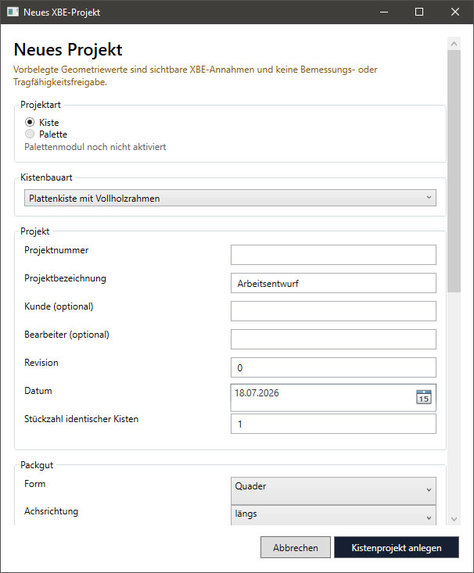
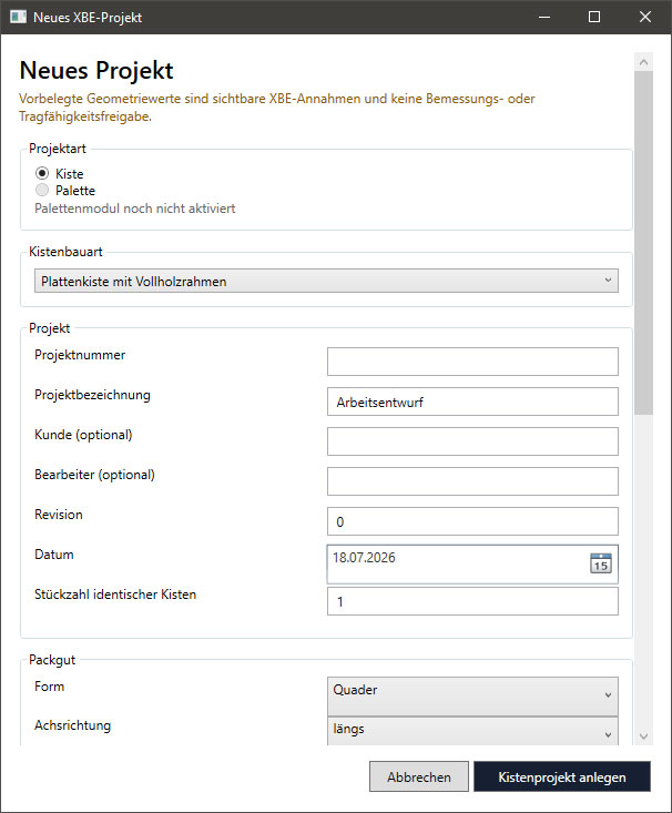
Create a New Project Start a new crate project by selecting the project type, crate construction, project details, quantity
-
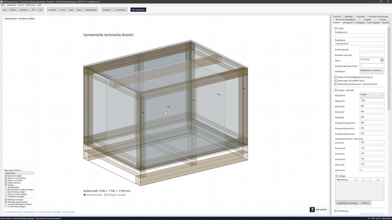
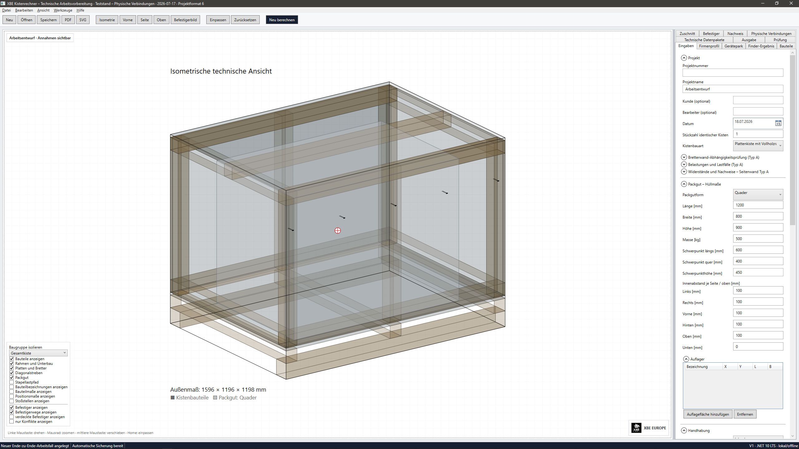
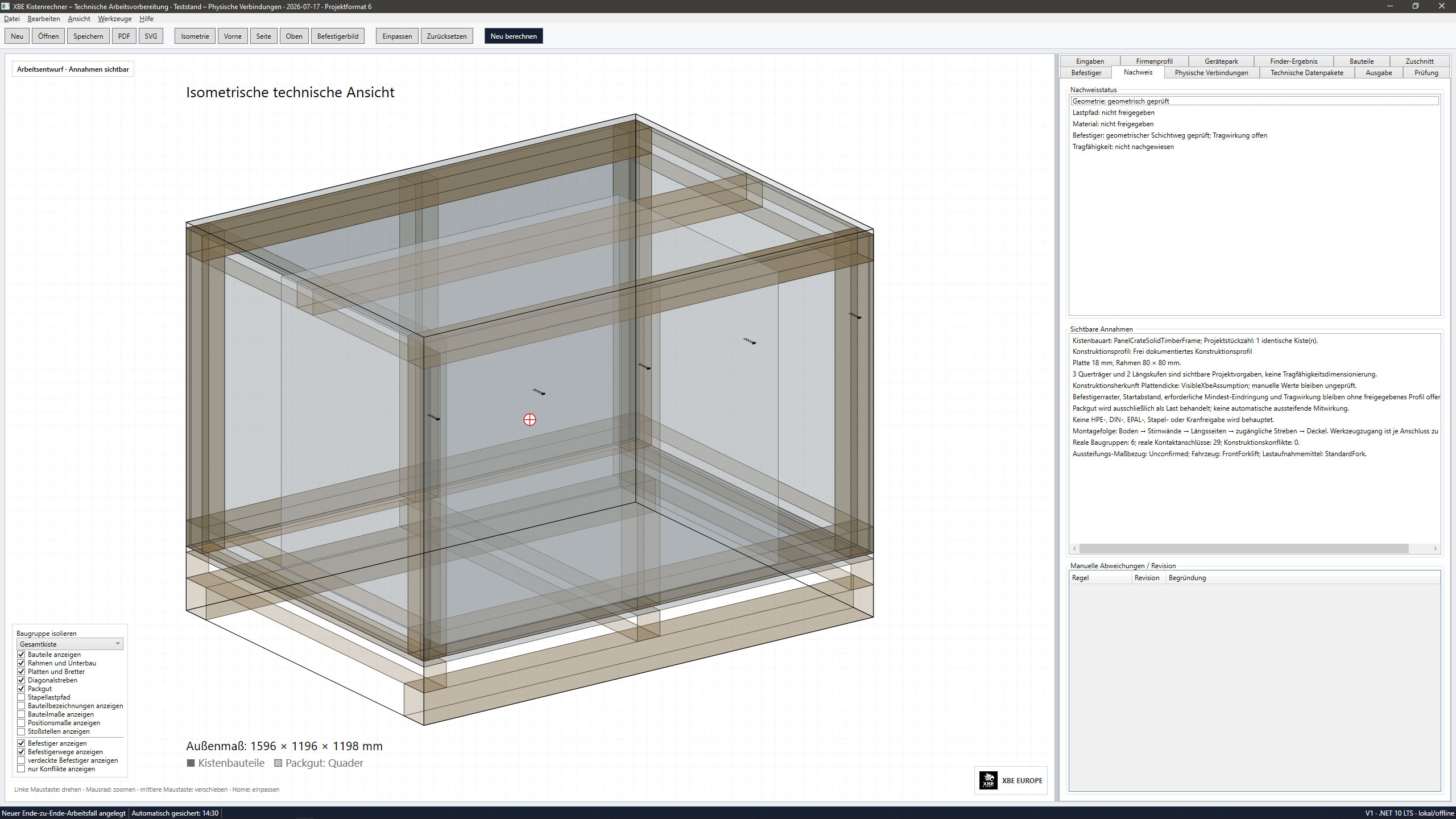
Interactive Engineering Workspace The main workspace combines a generated isometric crate model with project controls and technical data.
-
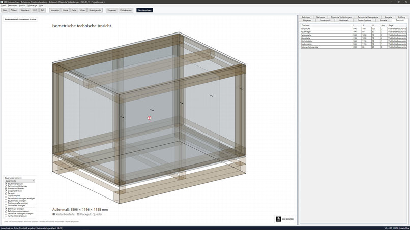
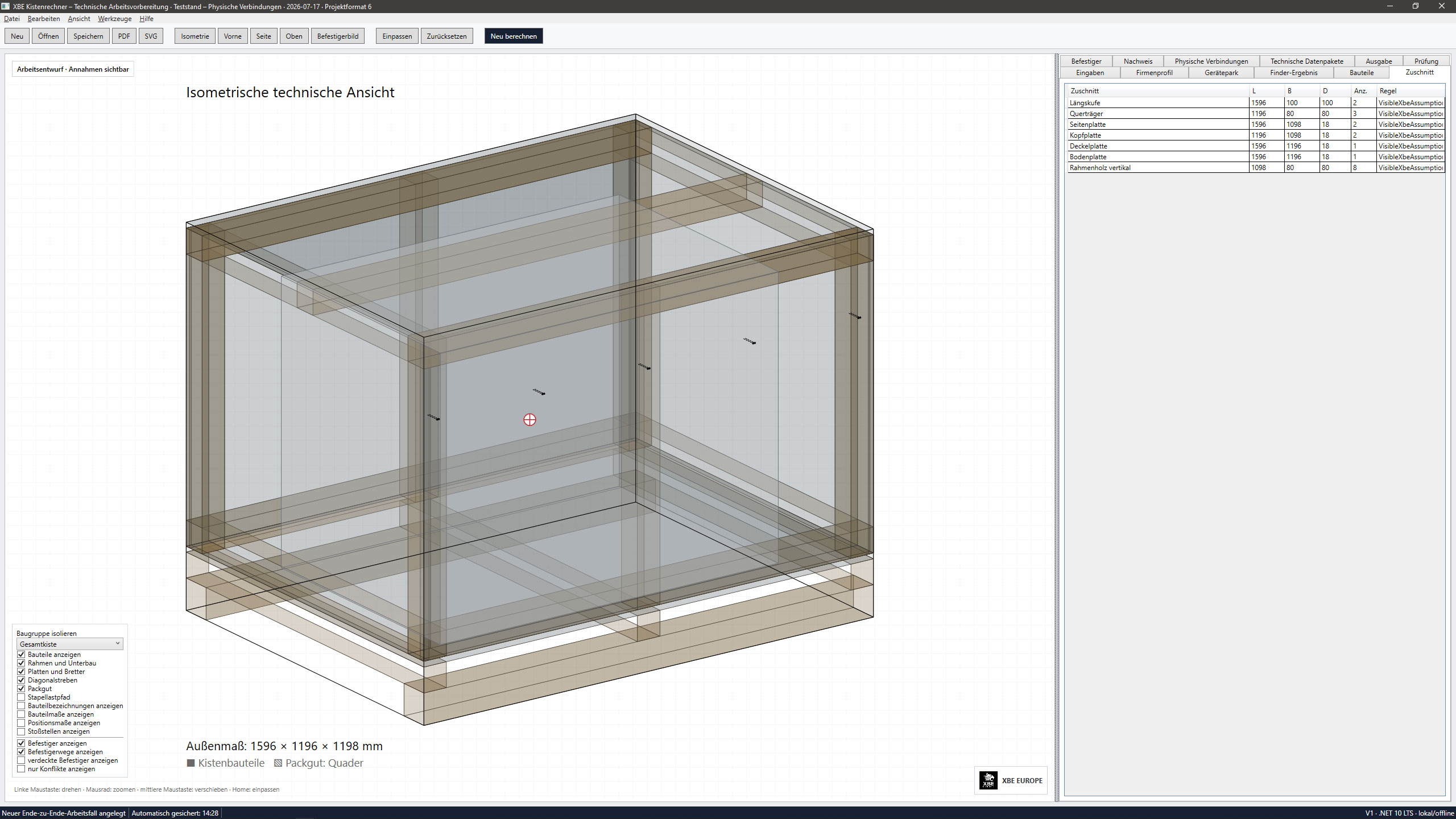
Automatically Generated Cut List The cut-list tab converts the current crate geometry into component dimensions and quantities for runners
-
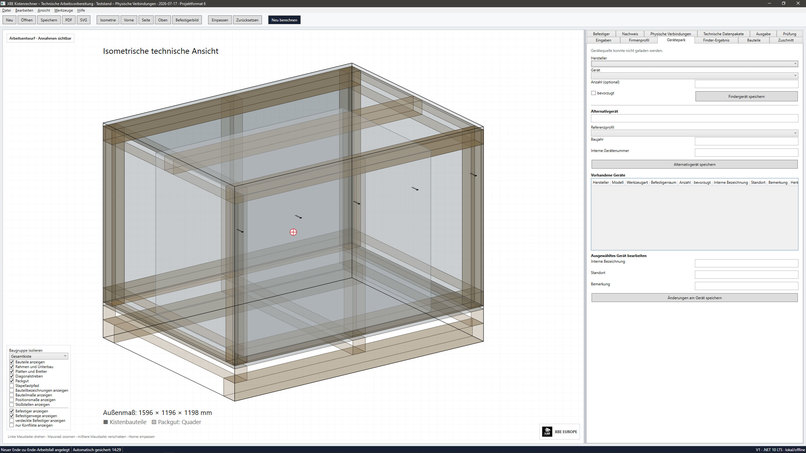
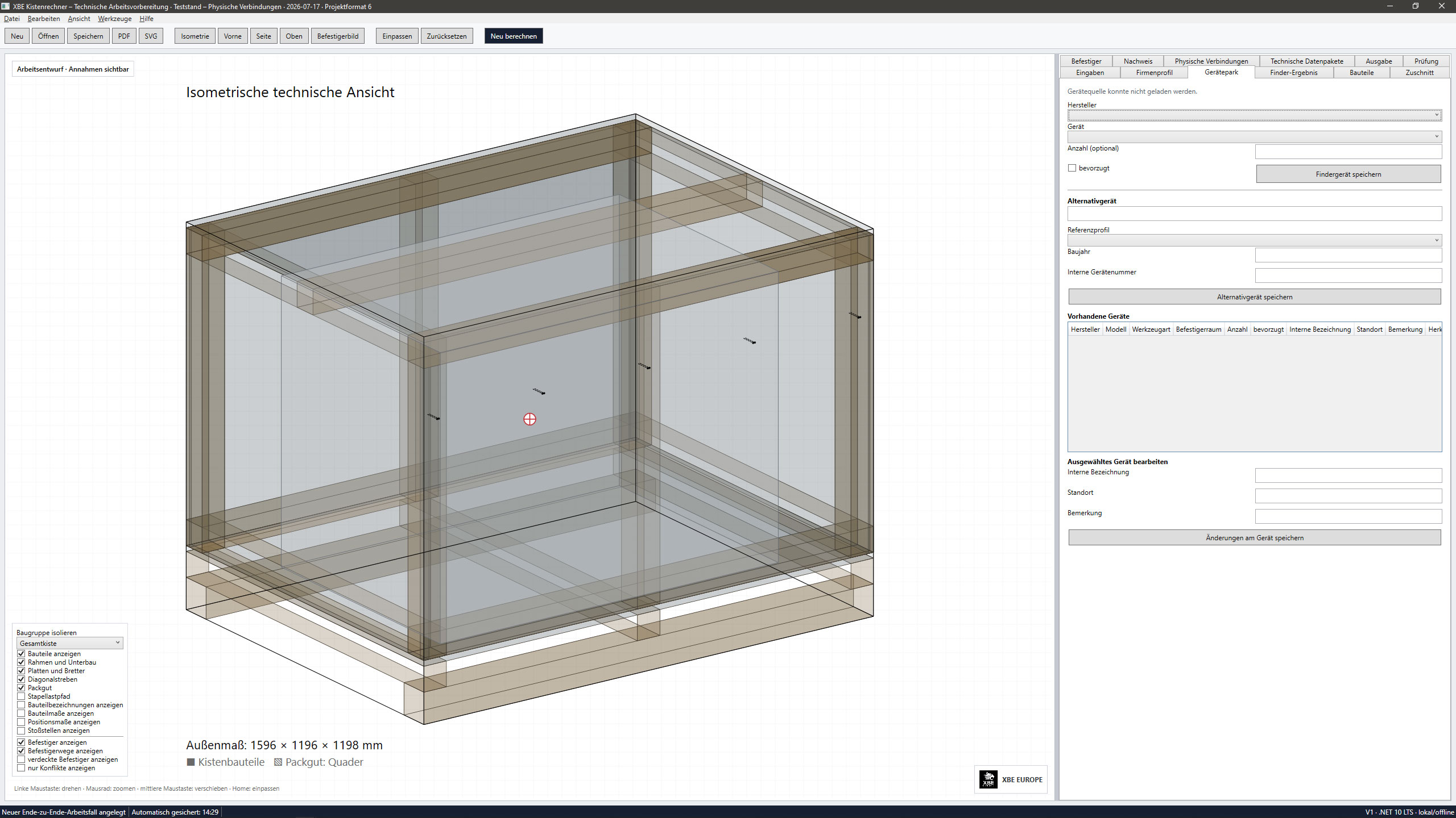
Local Device Park Users can maintain their available fastening equipment, preferred tools, quantities, locations and alternative devices.
-
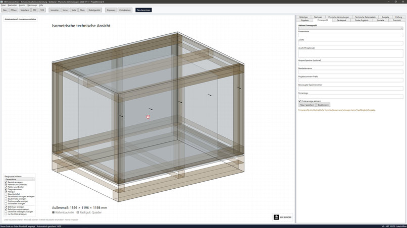
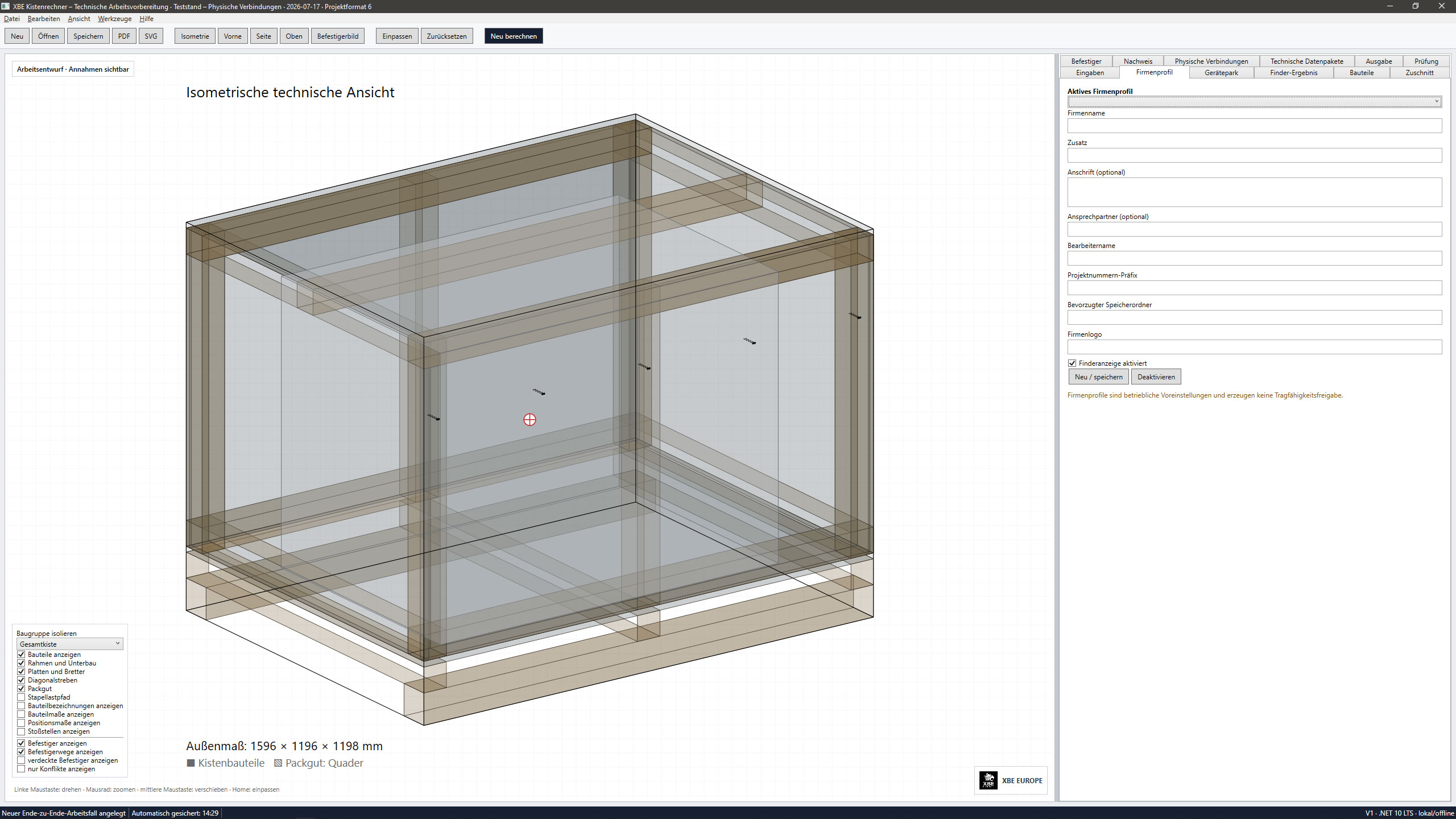
Reusable Company Profiles Company profiles store recurring information such as company name, contact details, operator, project-number
-
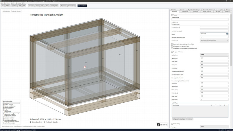
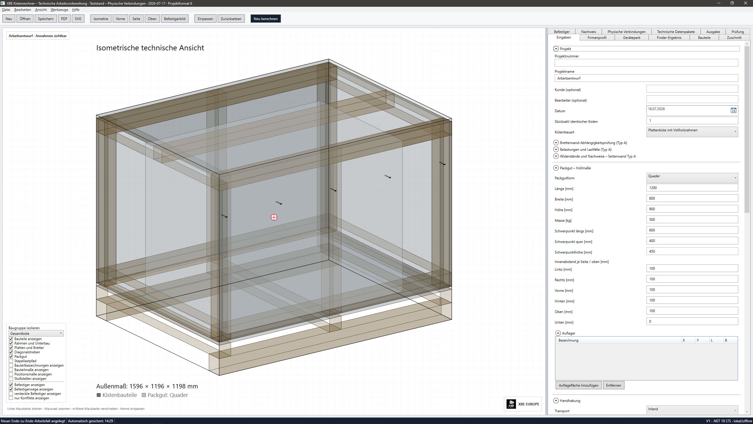
Project and Cargo Inputs The input tab records project data, crate type, cargo dimensions,
-
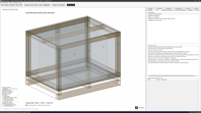
Verification Status and Visible Assumptions The verification tab clearly separates geometrically checked information
-
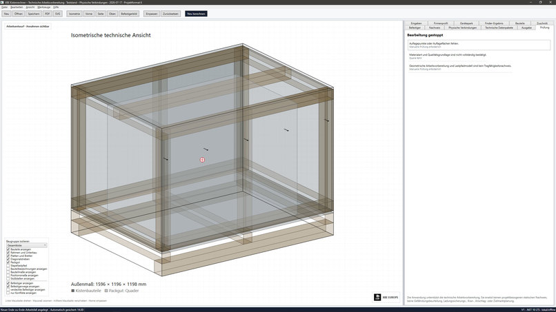
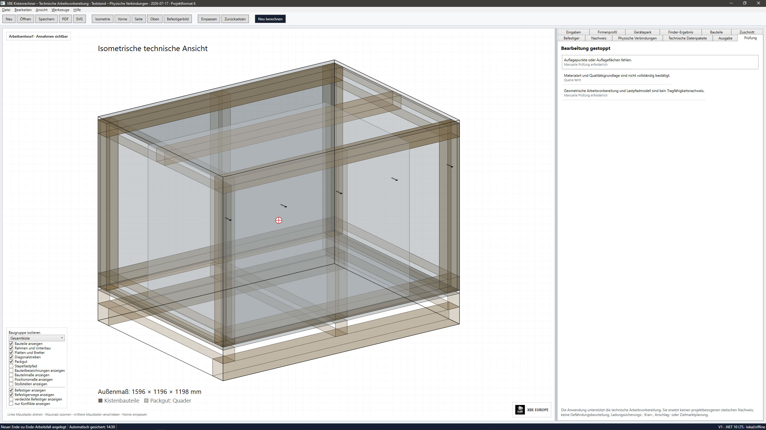
Safety Stops and Manual Review checking workflow stops when mandatory support data, material sources or engineering evidence are missing.
-
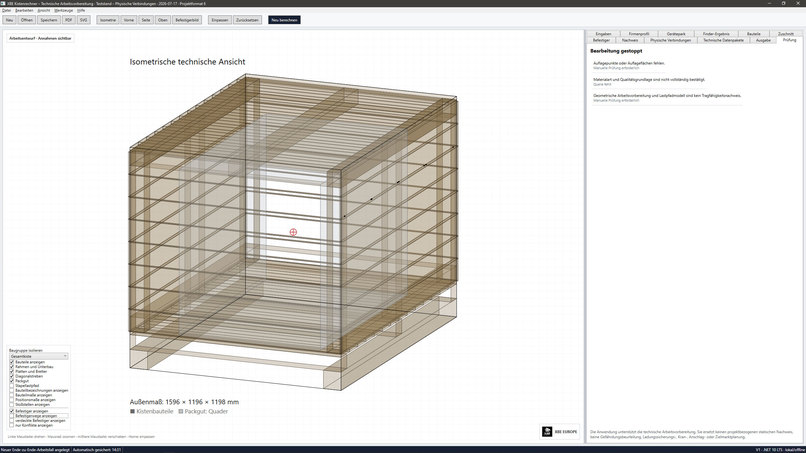
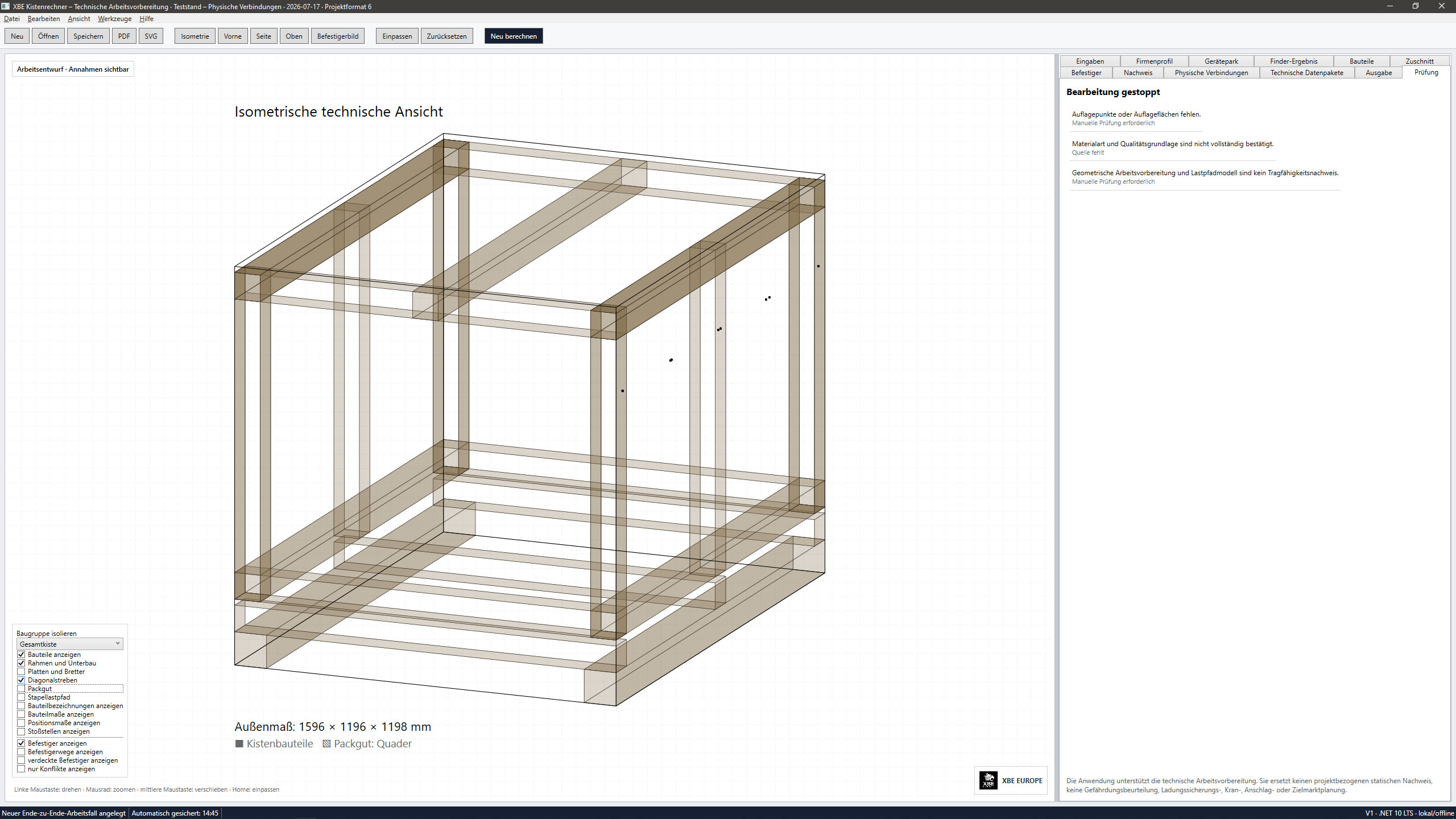
Open Protective Frame The application can generate an open protective-frame construction without closed wall panels.
-
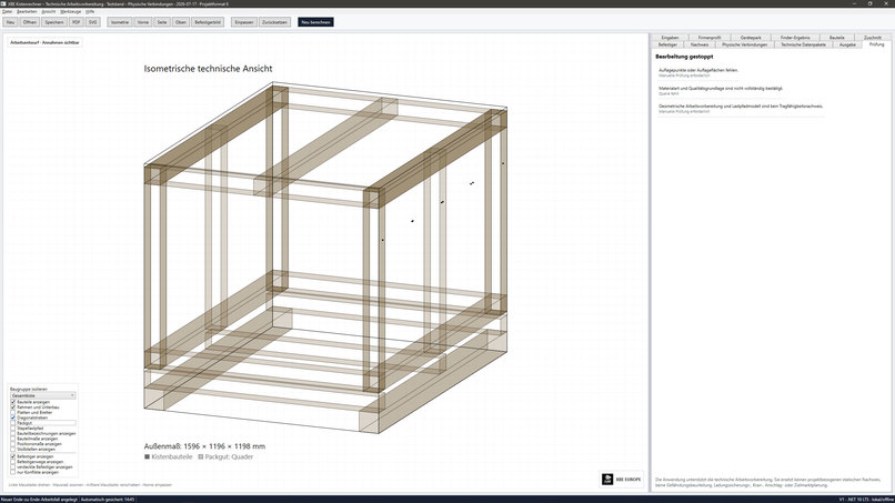
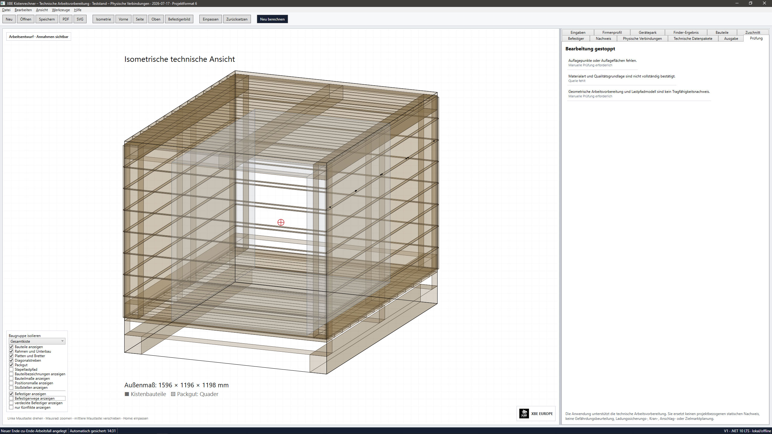
Alternative Crate Construction Type XBE can create different crate constructions from the same cargo and project data.
Inspiration
XBE Transport Crate Engineering was inspired by a real industrial problem: transport crates are still often planned through a combination of experience, sketches, spreadsheets, supplier documents, separate calculations, and manual corrections.
That approach can work for simple cases, but it becomes difficult when cargo is heavy, long, fragile, asymmetrical, export-sensitive, or has a high center of gravity. The crate geometry, supports, handling method, load paths, materials, fasteners, documentation, and transport conditions all influence each other.
The project grew from practical experience in industrial packaging, fastening technology, technical sales, logistics, and crate construction. Our goal was not to create a generic CAD demo. We wanted to turn practical crate-building knowledge into a structured engineering workflow that starts with the cargo and produces a traceable 3D transport-crate design.
What it does
XBE Transport Crate Engineering is a Windows desktop application for planning industrial transport crates.
The current build allows users to:
- create a new project,
- enter project and cargo information,
- define cargo dimensions, weight, clearances, center of gravity, and support conditions,
- select construction-related parameters,
- generate a three-dimensional transport-crate model,
- inspect the crate in isometric and technical views,
- show or hide structural groups and information layers,
- work through dedicated tabs for inputs, construction, connections, technical data, verification, and output,
- save and reopen project data.
The 3D view is more than a presentation model. It creates a shared spatial reference for the cargo, base structure, supports, walls, panels, framing, braces, dimensions, and future engineering checks.
The application is designed as a modular engineering platform:
- Module 1: industrial transport-crate design
- Module 2: planned pallet design and pallet-manufacturing workflows
The current version is a functional engineering prototype. It is not yet intended to replace final engineering approval, production drawings, or manual technical review.
How we built it
Development started on July 15, 2026, entirely within the OpenAI Build Week submission period.
The project was built completely with Codex and GPT-5.6 in an iterative repo-level development workflow.
Codex supported:
- application architecture,
- implementation of the Windows desktop interface,
- project creation and data handling,
- 3D rendering and view controls,
- connection of input fields to the project model,
- refactoring,
- debugging,
- validation logic,
- build repair,
- testing,
- and technical documentation.
The human contribution provided the domain knowledge:
- crate-construction principles,
- practical packaging requirements,
- fastening and connection logic,
- transport and handling scenarios,
- failure cases,
- technical corrections,
- priorities,
- and decisions about which calculations must remain blocked until verified.
The development process followed a repeated loop:
- Define a practical packaging requirement.
- Translate it into structured technical rules.
- Let Codex implement a bounded development step.
- Build and run the application.
- inspect the result technically and visually.
- Correct assumptions and regressions.
- Continue with the next verified step.
This collaboration was especially important because crate engineering cannot be reduced to one formula. Geometry, mass, center of gravity, supports, wall construction, materials, fasteners, handling, and load directions must be considered as a connected system.
Challenges we ran into
The greatest challenge was controlling the complexity of the engineering domain.
A crate may look correct in 3D while still containing:
- an invalid connection,
- insufficient clearance,
- an unsupported load path,
- an incorrect support condition,
- missing technical data,
- or a fastening arrangement that cannot yet be verified.
We therefore had to separate several different maturity states:
- fully implemented functions,
- implemented but not fully tested functions,
- partially implemented functions,
- prepared data structures,
- planned modules,
- and engineering checks that must remain blocked.
Another challenge was keeping the visual model synchronized with the technical project model. Changes to cargo dimensions, supports, structure, or construction type must remain consistent across the interface, stored project data, 3D representation, and future verification logic.
We also encountered normal software-development challenges:
- rendering errors,
- state synchronization,
- UI density,
- project-data changes,
- regression bugs,
- incomplete connections between modules,
- and the need to keep a highly technical workflow understandable.
One of the most important decisions was not to present incomplete engineering calculations as finished. Where the technical basis is not yet sufficiently verified, the application must warn, block, or require manual review instead of producing false certainty.
Accomplishments that we're proud of
We are proud that the project became a real, runnable Windows application within only a few days.
The current build is already more than a mockup:
- new projects can be created,
- project and cargo data can be entered,
- the main application tabs are functional,
- a 3D crate model is generated,
- the model can be inspected from different views,
- structural layers can be shown or hidden,
- and the project workflow is presented in one coherent interface.
We are also proud of the depth behind the visible interface. The application architecture is being prepared for:
- structured components and connections,
- persistent connection identities,
- load directions and load paths,
- cargo center-of-gravity data,
- support conditions,
- materials and fasteners,
- versioned technical data packages,
- validation states,
- warnings,
- and traceable engineering decisions.
Another accomplishment is the collaboration itself. Codex accelerated implementation, testing, debugging, and restructuring, while practical engineering experience continuously corrected assumptions and defined the boundaries of what the software is allowed to claim.
The result is not a generic “AI-generated crate.” It is the beginning of a specialist engineering tool based on real industrial workflows.
What we learned
We learned that Codex is most effective when it works together with strong domain expertise and clearly defined validation limits.
Codex can implement complex software very quickly, but speed alone is not enough in an engineering application. The quality of the result depends on:
- precise requirements,
- bounded tasks,
- repeated testing,
- expert corrections,
- traceable assumptions,
- and a clear distinction between implemented logic and technically approved logic.
We also learned that complex engineering knowledge must be converted into structured data and relationships before it can be automated reliably.
A useful crate-engineering application must understand more than dimensions. It must connect:
- cargo geometry,
- mass,
- center of gravity,
- supports,
- construction type,
- handling method,
- components,
- connections,
- materials,
- fasteners,
- and verification status.
Another important lesson was that a focused engineering tool can provide more practical value than a general-purpose CAD system when it guides the user through one real industrial workflow.
What's next for XBE Transport Crate Engineering
The next development stages will focus on completing and validating the engineering workflow.
Planned work includes:
- additional crate construction types,
- deeper physical connection modelling,
- improved fastener and connection verification,
- expanded material data,
- structured technical data packages,
- stronger warning and blocking logic,
- improved drawings and output documents,
- parts and fastener lists,
- clearer production and assembly information,
- broader testing with real crate-building scenarios,
- and validation by experienced industrial crate builders.
We also plan to develop Module 2 for pallet design and pallet manufacturing. This module will extend the same structured approach to pallet geometry, supports, handling, components, fasteners, manufacturing information, and technical output.
The long-term goal is to create a modular engineering platform that turns practical packaging knowledge into a transparent, reusable, and traceable digital process—from cargo data to a manufacturable transport solution.

Log in or sign up for Devpost to join the conversation.