-
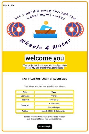
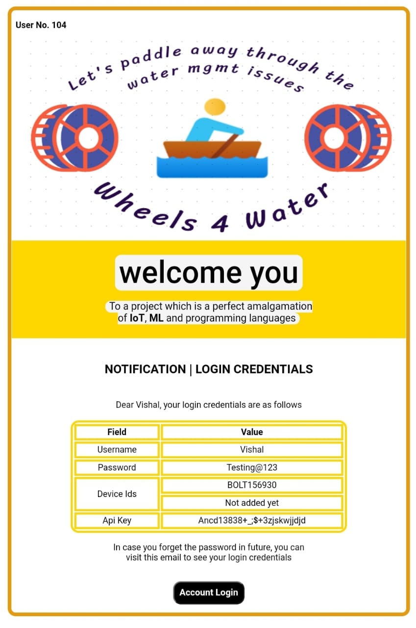
Automated Email Template (comes to every new user)
-
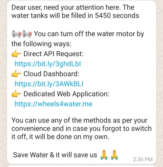
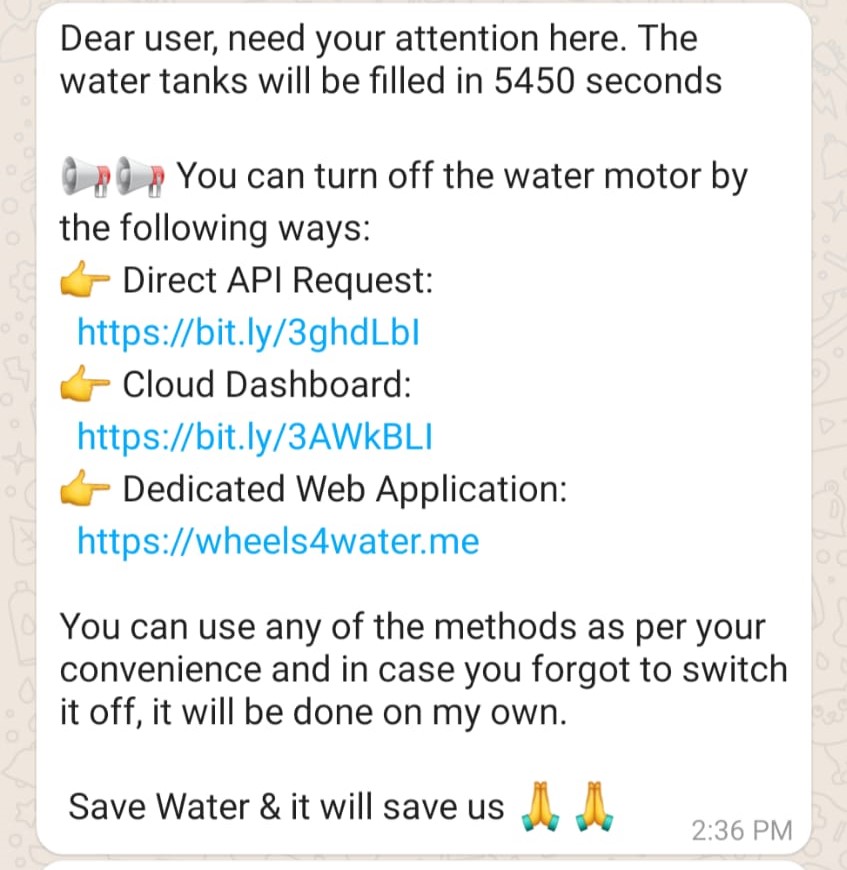
One of the 04 WhatsApp updates
-
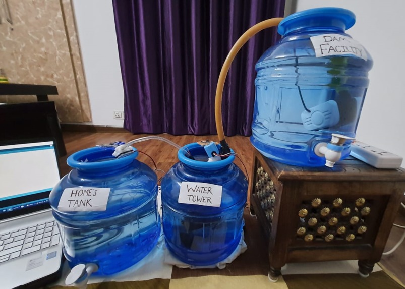
Physical appearance of the project
-
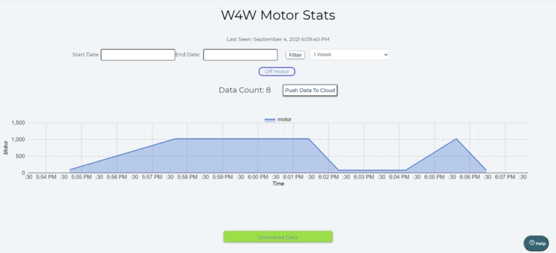
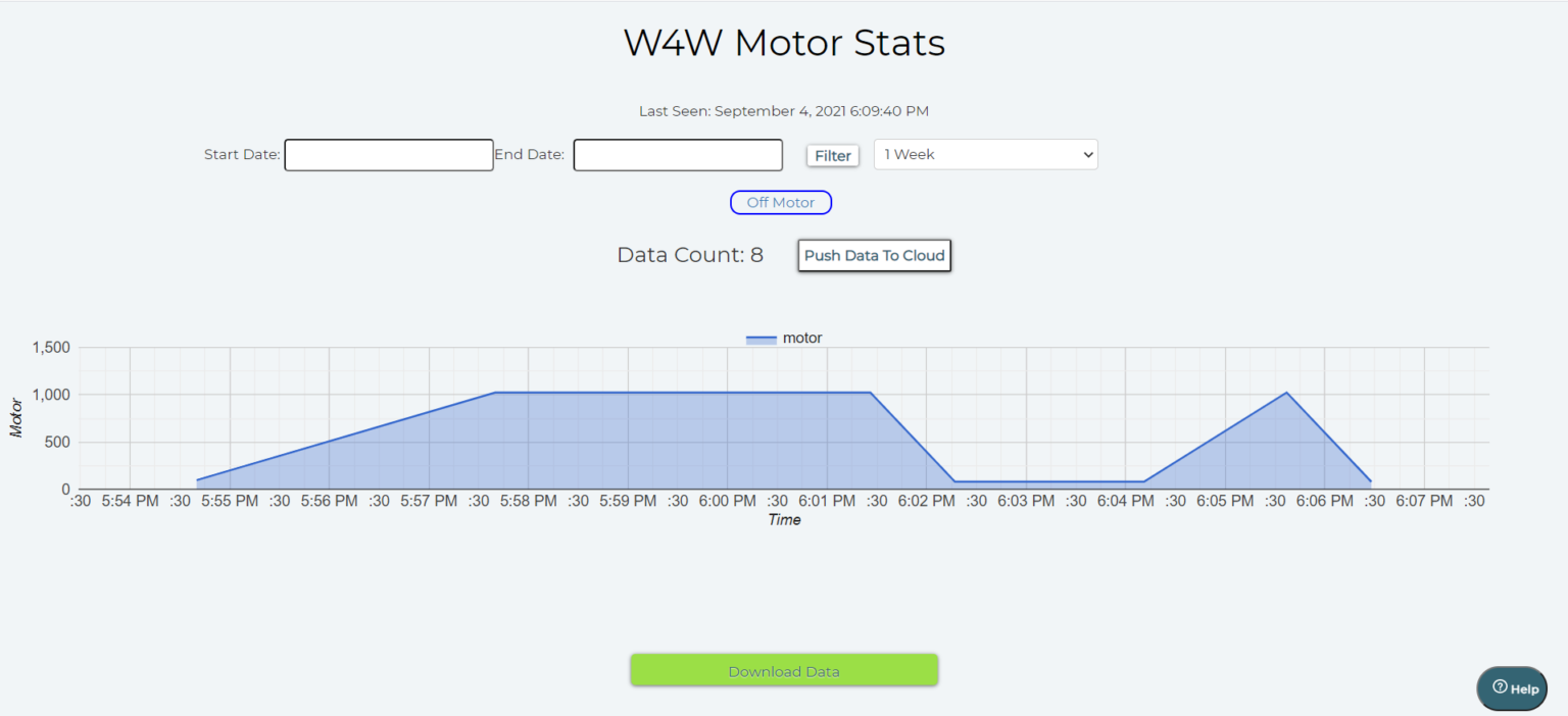
Cloud dashboard snippet

Inspiration
Water scarcity and water management topics are very closely related to each other. Improper water management leads to water scarcity and vice versa. Way before starting my IoT & Robotics journey I always wanted to solve the problem of overflowing water tanks. So, after understanding what do Internet of Things & Machine Learning means I thought of making a project which will eliminate this traditional problem to the full extent. But I was startled to see that there were already thousands of projects covering this area. Almost every sensor out there has been used in these projects.
What it does
I wanted to make a project which must be very different from the existing projects. Then I came up with the project Wheels 4 Water, a perfect amalgamation of IoT, Machine Learning & Cloud. Let me point the main highlights of our project, which makes the project stand out from others.
Apart from the basic sensors, I have used many different sensors. Be it a water flow sensor, solenoid valve, or an analog multiplexer IC (CD4051), all these sensors helped us to almost nullify the water wastage through the whole water supply chain. In this manner, I focused on the whole water supply chain.
At every instance of the project execution, the end-user will be updated and informed about each major workflow. The project will talk with the user. Thus making the project active.
In order to make this project more interactive, I dumped the old idea of integrating IFTTT or using the CLI. Even I have not used either the blynk application or the normal switches in our project. Instead of all this, I have provided four custom options to control the project which include a dedicated website, NodeMCU based robot, customized cloud dashboard & voice control (I have not used any drag and drop feature of Blynk or IFTTT applications)
Rather than using simple and pre-built ML systems I used the Iterative Dichotomiser 3 algorithm and implemented it via Python so that the robot can actually make decisions on its own after analyzing the dataset.
Sensors Used With Arduino 5V Relay, I2C LCD, Arduino Uno R3, 9V Battery, Bolt Wi-fi Module(in our case), IRF540 MOSFET, Water Flow Sensor, Ultrasonic Sensor X 2, 1N4007, Rectifier Diode, 12V DC Solenoid Valve, Water Lifting Submersible Pump, 4-way Capacitive Touch Switch Module, 3-6 V Mini Micro Submersible Water Pump
Sensors Used With ESP8266 (Nodemcu v1.0) Nodemcu, Piezo Buzzer, IR Sensor X 2, DC Motors X 2, 12V DC Adapter,TCS3200 Color Sensor, Capacitive Touch Sensor, ESP8266 Motor, Driver Shield, Analog Multiplexer IC – CD4051
How I built it
One can break down my project into two major parts. One is the immobile Arduino and the mobile NodeMCU based robot. I will discuss the functioning of each of both sections.
Arduino In the project there are 03 water tanks (which sorts of replicate the real world scenario). You can assume the first one to be the main water facility, the second one to be the nearest water tower, and the third one to be the water tanks in homes. The main water facility will get the water from the dam and the water lifting submersible pump will be turned ON and at that point of time the solenoid valve will be turned LOW. Whenever the water level in the nearest water tower will be less than 20% then the solenoid valve will turn ON and thus the water tower will get filled to a certain threshold (say 95%). When the water tower will be filled then the DC water motor will start pumping out the water from the tower to the water tanks in our home.
One major aspect of the Arduino setup is that I have to make the Arduino and the python program communicate with each other. I have to do this as WiFi Module (Bolt's wi-fi module in our case) can understand Python language, not Arduino’s language. So, I have to make the Arduino pass some certain keywords to the Python program and then the Python program will act accordingly. For this, I used serial communication through the COM port. This was a tricky part as the Arduino has to pass about 6 parameters to the python program and then python program has to procced accordingly.
Nodemcu Based Robot The first work for the robot is to fetch the place attribute so that it can find the place where it has to go. Once the robot fetches that value then the TCS3200 color sensor comes into the picture. Basically in the dataset, there are 03 values for place attribute which are balcony, bedroom, and hall. From the starting point of the robot to the final destination I had laid down 03 different colored lines so that the color sensor will follow a particular colored line after getting the predicted value. The place has the following colors:
- Red - Bedroom
- Green - Hall
- Blue - Balcony
I am laying out a table that tells the working of each file:
- robot.ino: Catch the users’ input & reach the predicted place
- arduino.ino: Serial comm with python & data collection
The above-listed Arduino files are for Arduino and NodeMCU respectively. The below-listed files are python files that do the manipulation with the dataset and then upload/fetch the same via Integromat.
- attribute.py: Gathers values for the data points to be pushed in ID3 algorithm
- credentials.py: Stores API keys, SSIDs, authentication variables
- integromat.py: Retrieval of information from Integromat’s scenarios
- prediction.py: Collect the attributes and uses the ML algorithm to predict the place
- project.py: Main file which ensures smooth functioning of the project
The best understanding of the code will be through the working video of the project. So, do look at the working video of the project at the start of this documentation.
Using the ESP8266 motor shield was difficult because in the shield’s official datasheet nothing is clearly explained. But after several repeated attempts I sorted the overall functioning of the shield. NodeMCU is placed on the top of the shield so that both become one in the other. A total of 2 DC motors can be connected so that is why I used a 02 wheeled robot which was controlled through the DC motors while the Caster wheel provides the stability to the overall chassis. As I used 02 12V DC motors I have to either use a 12V DC cell combination or can use a 12V DC power adapter to power up the motors. The major drawback of using the 12V cell combination was that the cells get discharged very quickly so this option doesn’t seem viable at that moment. That’s why I turned up for the 12V DC adapter solution as it seamlessly provides enough power to the motor shield and motors. Do note that I have short-circuited the Vin and Vm pins of the motor shield so that the power coming from the motors can also be utilized for powering up NodeMCU.
Using the multiplexer IC with the motor driver shield was also quite a bit of a challenge as the CD4051 multiplexer IC is basically a 03 select line-based (S0, S1, and S2) multiplexer. This means that I can insert 2^3 = 8 analog sensors with this IC and use the single port i.e. A0 of the NodeMCU to read all 8 values. But in my case, I used only 2 IR sensors which means I don’t know what I have to do with the third select pins? In many attempts, the third select line was giving random values which were not even needed. After some trials, I got to know that the third select line must be provided a voltage of 0 so that the pin should not float.
While using the Integromat scenarios, I was not sure how to create a scenario and how to integrate in our programming? I used 6 scenarios for the project which includes various CRUD operations. It was challenging to get the response in the Nodemcu because the response there comes in a format which needs to separated as per our needs. So, it was good to deliver the working scenarios.
Accomplishments that I'm proud of
As already mentioned in the starting that I will be creating 4 custom options for the project and I did that. I have created the website, incorporated the capacitive touch sensor, automated the voice control thing and created the cloud dashboard.
This is a project which can be deployed in the market as it is almost optimized. It is also cost-efficient as the whole hardware setup costs around $130. As in the real world, the magnitude of the sensors will be increased, so that the cost will only reach up to $300 (which is a quite remarkable feat).
I have magnificently solved an old-age problem of water management by incorporating about 30 electrical components together and making a project which can be either used by a single person or by the entire community.
I have made all the videos and the images for the project by our own. This one is also special because this was an area out of our expertise and I am sure that the videos and the images brings the best out of the project. The hardwork of our team rightly reflects in each of the project's component i.e. website, software and hardware configurations and the actual working of the project.
NOTE
For each major step in the processing, the user must be intimated regarding the same. The user will receive notifications when the motor motor will be turned ON, how much time to fill it will take, what are the 04 options through which user can turn it OFF and, when the motor will be turned OFF (either automatically or through the user's input). A total of 04 WhatsApp updates will be posted on the user’s registered number. But what if there is no Internet connectivity with the user? Then, in this case, 04 normal text SMS will be also sent which makes the project more relatable to the real world. All these notifications related work is done through TWILIO'S API.
What I learned
I learned how the problem should be broken down? In the last 1 and a half days, I coded the website, rectified the major portion of CPP (Arduino coding) and thus I rightly managed my time. I shaped my thoughts into reality and are sure that this project can be launched into the market to cater the needs of many people.
Talking about the technical part, I learnt how to make a beautiful fully functional website and also got to know about the hosting services. Starting form the cloud I got to know about CRON jobs and many other things which helped me making an automated project.
What's next for Wheels4Water
As this project will be directly accessible to the users, I am trying to add a feature in the website through which the user can contact with me and therefore I can make the proper arrangements for setting up the hardware as per the user needs. Also, as the activity of the robot is being updated in a Google sheet, I will be giving the user an option to download the report on a weekly basis.


Log in or sign up for Devpost to join the conversation.