-
-
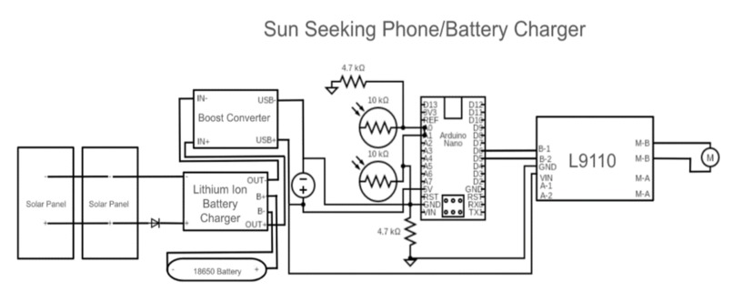
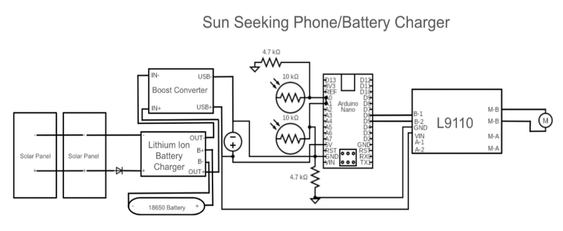
Schematic
Inspiration
Imagine a world where everyone has access to clean, renewable energy to power their electronic devices. The Sun Seeking Phone/Battery Charger makes use of the limitless energy of the sun, harnessing the solar energy to its full potential through light dependant resistors (LDRs) and a gear motor to reduce our reliance on non-renewable energy sources and contributing to the fight against climate change. By providing a constant source of clean energy and making sure it harnesses solar energy to its full potential, this project has the potential to make a substantial impact on sustainability efforts globally.
What it does
The solar panels are connected to a TP4056 Lithium Battery Charger Board. There is a diode behind the solar panels to make sure the current flows in one way. The TP4056 board has its light on, meaning solar energy is being converted to electrical and that the battery is charging. It charges the battery through Constant current/constant voltage charging. Initially, the charger provides a constant current to the battery, typically until the battery reaches a predetermined voltage level. During this phase, the current remains constant, allowing the battery to charge rapidly. The charger transitions into the constant voltage mode once the battery voltage reaches the predetermined level. In this phase, the charger maintains a constant voltage across the battery terminals. The current gradually decreases as the battery charges, and eventually, it reaches a very low level, indicating that the battery is fully charged. It is also connected to a switch, which controls the rest of the circuitry. While the switch is off, it only charges the battery, if its on, the 5v 1 amp step-up boost converter is on, so you can charge your phone and other electronics that use a USB port, and it also provides power for arduino, which plays a role in the solar tracking component. The switch will almost always be on, except for when you only need to charge the battery or for troubleshooting. Now for the solar tracking part. If I were to block the left LDR, the motor will turn in the right direction because that is where the most light is. Similarly, if I block the other side, the motor moves in the other direction. That is basically what the PCB does. The motor here works through the l9110 motor control board. When A1 is HIGH and A2 is LOW, the motor rotates in one direction. When A1 is LOW and A2 is HIGH, the motor rotates in the opposite direction. When both A1 and A2 are HIGH or LOW, the motor is in a braking state (same with B1 and B2). The more voltage you send to the motor, the faster it turns to that side. Thus, you can use (PWM) signals to vary the average voltage applied to the motor, thereby controlling its speed. Now for the code, pins 5 and 6 are used for the motor because they support PWM. In the loop function, the code continuously reads the analog sensor values from pins A0 and A1, which are connected to the left and right LDRs. These LDRs detect the intensity of sunlight falling on them, providing values between 0 and 1023 via the analogRead(). Then, the code compares the sensor readings to determine the necessary adjustment for the solar tracker's position. It calculates the difference between the readings from the left and right sensors and compares it with a predefined deadband value (80), which acts as a tolerance range for considering the sensor readings similar. If it detects more on say the left side, it would move to that side by applying power to the left motor pin using analog right, and vice versa. If both light levels are within the deadband, both motor pins are grounded to maintain the tracker's current position. The power level for motor control is set to 200 because the sun moves pretty slowly across the sky so it doesn’t have to be too fast.
How we built it
Our project integrates various components into a cohesive system that efficiently charges devices using solar energy. The 3D-printed case is divided into multiple sections to accommodate all the necessary parts. The left subsection contains the Arduino Nano and its associated circuitry, all mounted on a ¼ Perma-Proto board supported by two cylinders. This subsection also includes the 5V 1-amp step-up boost converter with its USB port facing forward for easy access. The right section houses the lithium-ion battery charger with wires extending through a small hole to connect to the battery below. The L9110 motor driver is also situated here, connecting to the motor in the middle section through interconnecting holes. The middle section houses the gear motor connected to another 3d printed cylinder base to rotate the solar panels for optimal sunlight exposure. It also contains 2 wire junctions to connect the left and right sections and a square hole for the PCB (containing the LDRs) for solar tracking. The PCB, placed in the middle, tracks voltage changes using two LDRs connected as per the schematic that I've created. It features a terminal block with pins for Vcc, Gnd, A0, and A1, and 2.2 kΩ surface mount resistors for accurate voltage division. The PCB includes silkscreen writing for personalization, with copper routing done on both the top and bottom to prevent wire overlap.
Challenges we ran into
Ensuring that all components fit neatly into the designated sections of the 3D-printed case while still being functional took some effort, but the results made up for the challenge. It took some time to achieve accurate readings from the LDRs for the gear motors to turn, and after many trials and errors, I realized the need to lower the value of power to 200 (instead of 255) and the need to add a deadband value (of 80) as its hard for the voltage values to be the same. Another problem was balancing the power distribution between the USB devices and the lithium-ion battery because every time I charged a phone, everything would turn off. However, I realized that the lithium-ion battery charger that I ordered was a fake and I had to order the actual one. Once I used that charger, everything worked perfectly.
Accomplishments that we're proud of
I am proud of the dual charging capability my project has, as it can simultaneously charge USB devices and a lithium-ion battery. This ensures continuous power availability for multiple devices, enhancing the practicality of our solution. I am also proud of my innovative design that successfully integrates all components into a compact, scalable, and user-friendly structure. This thoughtful design approach not only makes the system efficient but also easy to use. Lastly, I take pride in contributing to environmental sustainability by providing a practical solution for renewable energy use, harnessing solar energy to its full potential.
What we learned
I learned the importance of calibration, as accurate calibration of the LDRs is crucial for optimal performance of the project, which was implemented into the code. I also realized the importance of efficient power management, as it is essential to ensure that all components of the system receive adequate power without overloading any part. I also learned about constant current/constant voltage charging which helps me understand how batteries can be efficiently charged while preventing overcharging.
What's next for Sun Seeking Phone/Battery Charger
The best part about this project is that it can be easily scaled up with higher wattage solar panels and larger gear motors, allowing for faster charging of batteries and electronic devices. To compensate for this voltage increase, a L298N motor driver board should be uses as it can handle higher voltages and currents compared to the L9110, providing more robust control over larger gear motors. This allows for smoother and more reliable solar tracking movements. We can also put the boost convertors in parallel to allow for multiple devices to be charged at once. Furthermore, the existing code can remain unchanged with these hardware upgrades, simplifying the scaling process, proving the versatility of this project.
Built With
- 18650battery
- 5vstepupboostconverter
- arduino
- autodesk-fusion-360
- gearmotor
- l9110
- ldr
- pcb
- solarpanel
- tp4056


Log in or sign up for Devpost to join the conversation.