Inspiration
With the COVID spreading across the world, we need to stay at home from time to time. However, it was boring to stay in door all the time. One day, I came up with an idea to create a man-made weather scenery at home. Thus, this project is to build a scenery to remind people good old days when we can freely play outside. First, it can show the date, time, room temperature and weather mode on LCD display. Second, it can simulate the weather within the potted landscape in the small box.
What it does
The project works as a desk décor which is placed on the desk or at various indoor places. The temperature sensor as an input device can measure the room temperature. In addition, the weather mode in our system and real time information of the area can be transmitted to the controller. In this system, it has three modes of weather: sunny, rainy and windy. The system can print the indoor temperature, current weather mode, time and date on the display. Users can get the room temperature and time directly with our project.
How we built it
There are 5 modules in this system, accessories were not included in discussion such as resistors, LEDs (for monitoring sensor status), landscape, plastic box, and transistor (for actuators) are not included.
We will use a wireless module to control and switch the weather mode of the weather clock. The computer will justify the information and trigger the different mode build-in the MCU.
In sunny mode, the MCU will control timer 1 to generate a PWM wave to the transistor to control the intensity of the LED light. The duty cycle of the wave can be changed with the sunlight intensity. To control the sunlight intensity by a joystick, ADC is required.
In rainy mode, the MCU will be triggered and send signal to the transistor and turn on the water pump.
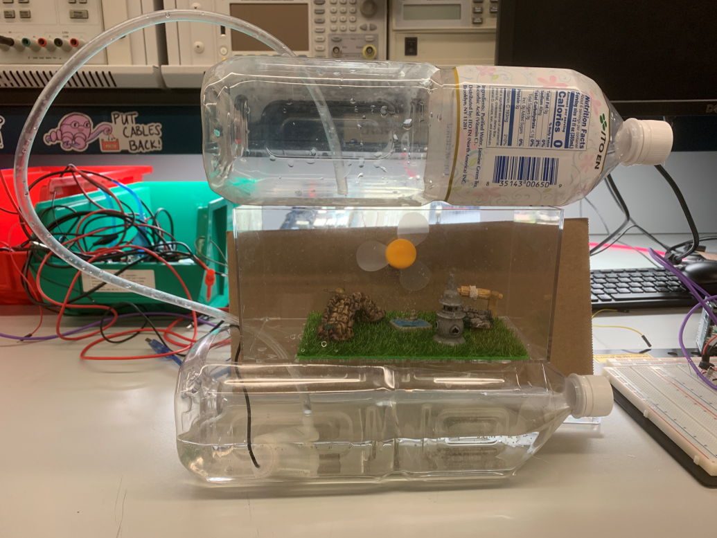
In windy mode, the MCU will be triggered and send signal to the transistor and turn on the fan.
In LCD screen module, the indoor temperature is obtained by temperature sensor module. To read the signals sent back from the temperature sensor, it is indispensable to use ADC. Plus, the current time and date is acquired by the DS1307 (i.e. the Real time Module). To achieve the communication between the RTC and MCU, I2C communication protocol is essential. Additionally, the information of weather mode can be controlled by the wireless module and be printed on the LCD screen. Serial communication (SPI) is applied to drive the LCD screen.
Finally, components are integrated together.
Challenges we ran into
Before this project, we thought the actuators could be easily connected into the circuit. However, the real situation was totally another thing. Although the actuators have same working voltage on datasheet, the working current are totally different. After several failure, we finally figure out three different circuit to protect actuators to ensure them safely work. Also, the communication between the Arduino and the real time module was a big problem. We used the SPI and I2C protocol to solve the problem.
Accomplishments that we're proud of
In this project, the weather clock is worked well: when the switch is pressed, the LED, fan and the water will be worked to present the current weather mode. LCD display system will show the room temperature as well as the time, which will be a reliable clock. All in all, our weather clock system will be a great décor on your desk.
What we learned
By building the firmware from the scratch, building the circuit and adjust the real time module, we were able to take a deeper insight into the power management, ADC, wireless communication, and serial communication. It has also been a great learning experience to learn to interface the different serial protocols such as I2C and SPI.
What's next for Weather Clock
The further developments of the system could be: importing the weather information to the Arduino and printing it on the LCD screen. We would also say that this project is still not entirely completed because we used lots of jump wire to avoid the tricky soldering work. Building a circuit that can work on a breadboard is much simpler, but such a circuit is really fragile. We plan to integrate all the wire on a PCB board in the future.

Log in or sign up for Devpost to join the conversation.