-
-
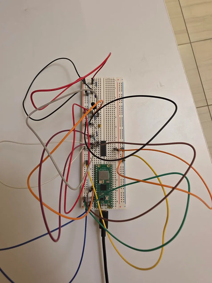
Breadboard
-
Inspiration
Wearables and pulse oximeters cost $30 to $100 or more, which puts them out of reach for many students, schools, and under-resourced settings. They also hide how the measurement works. Every smartwatch relies on the same idea: shine light into skin and watch how it changes with each heartbeat, a technique called photoplethysmography (PPG). We wanted to build that sensor ourselves from loose components, with no pre-built sensor, and understand every step from the light to the signal to the BPM.
What it does
Place a fingertip between an infrared LED and a detector. Each heartbeat briefly increases the blood volume in the fingertip, which changes the light reaching the detector by only about 1%. Our circuit amplifies and filters that tiny change, a Raspberry Pi Pico samples it at 100 Hz, and our software turns it into a live heart rate on a web dashboard with a real-time waveform.
The device also checks its own signal quality. If the finger is loose, the signal is clipped, or the rhythm is unsteady, it shows a warning instead of a wrong number.
Who it's for
- Students and athletes: a low-cost way to check resting and post-exercise heart rate without a wearable.
- Schools and low-resource settings: the parts cost only a few dollars, so it can work where a $30 to $100 oximeter isn't practical.
- Teachers and intro bioengineering classes: it shows every step of how a pulse sensor works, from light to signal to BPM.
- Makers and hobbyists: open code and a parts list that anyone can rebuild from the kit components.
How we built it
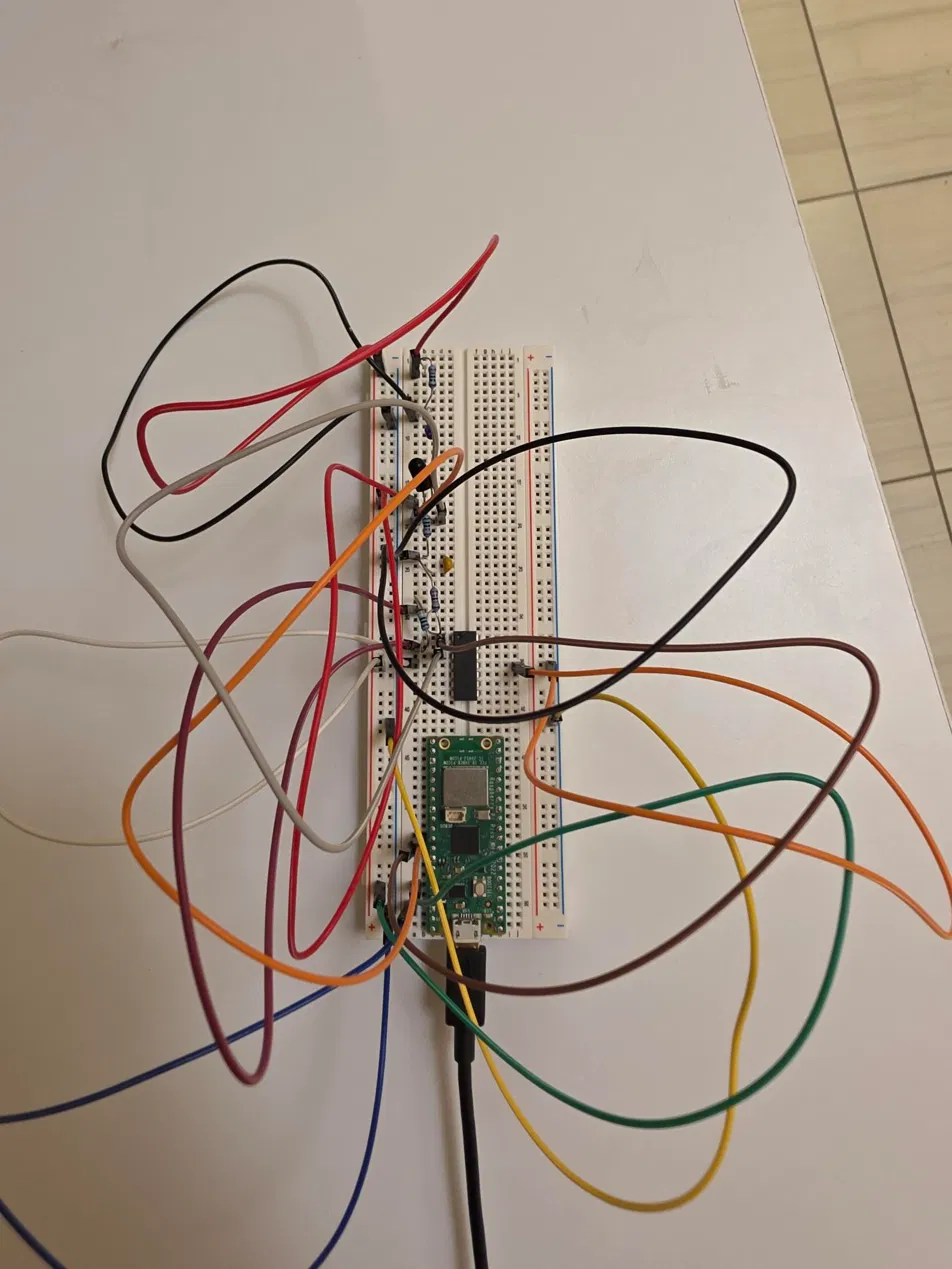
Hardware. A TSAL4400 infrared LED shines through the fingertip onto an LTR-3208E phototransistor. A load resistor converts the detector's tiny current into a voltage. An MCP6004 op-amp provides gain and filtering. Its non-inverting stage has a gain of
$$G = 1 + \frac{R_f}{R_g} = 1 + \frac{1\,\text{M}\Omega}{220\,\text{k}\Omega} \approx 5.5$$
A high-pass stage removes the large steady (DC) light level, with a corner frequency of about
$$f_c = \frac{1}{2\pi RC} = \frac{1}{2\pi \cdot 220\,\text{k}\Omega \cdot 10\,\mu\text{F}} \approx 0.07\ \text{Hz}$$
and a low-pass stage near 7 Hz removes high-frequency noise, leaving the band where heartbeats live.
Firmware and software. MicroPython on the Raspberry Pi Pico samples the signal at 100 Hz. Software applies a band-pass filter (about 0.7 to 3.5 Hz, roughly 42 to 210 beats per minute), detects each beat, and computes heart rate from the median beat interval:
$$\text{BPM} = \frac{60}{\text{median beat interval (s)}}$$
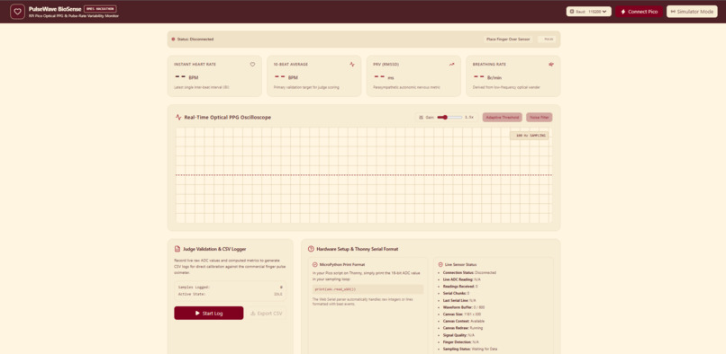
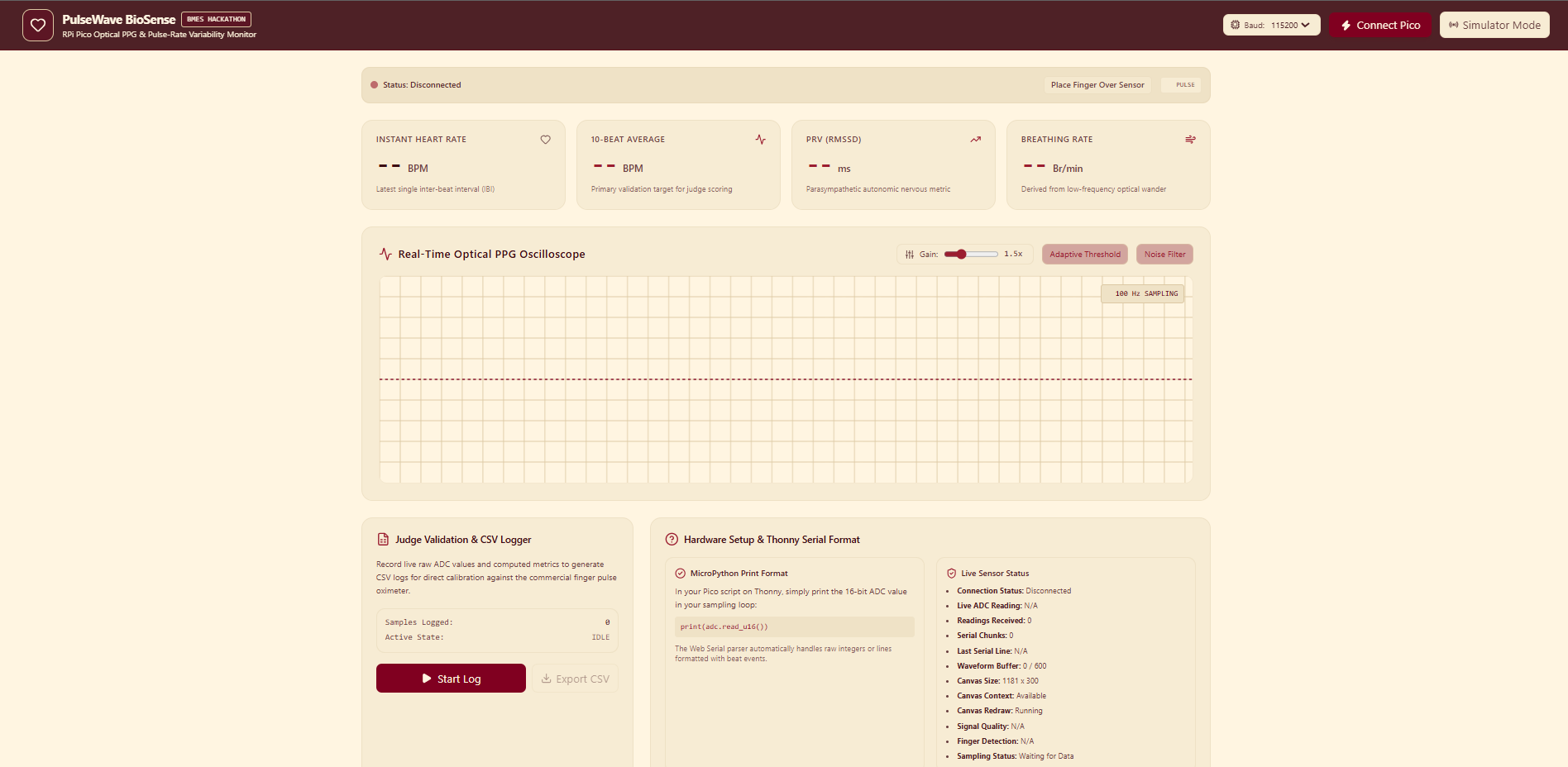
Quality checks reject low light, clipping, and unsteady rhythms before a number is shown. A React and Vite dashboard displays the live waveform, the heart rate, and the signal-quality status.
What we tested
We tested the sensor on our own fingertips and saw a clear, repeating pulse waveform and consistent heart rates across teammates. We have not yet completed a formal comparison against a reference pulse oximeter, so we are not claiming a measured accuracy. The comparison at the expo will be our first formal accuracy check.
Challenges we ran into
- A flat signal. Our first build read about 0.01 V and showed no pulse at all. Instead of guessing, we debugged it one stage at a time: we checked that the LED was emitting infrared by viewing it through a phone camera, tested the detector on its own, and checked the power rails. We found the detector's load resistor was far too small to produce a usable voltage. Changing it from 10 kΩ to 220 kΩ brought the signal to life.
- A tiny signal on a large baseline. The pulse is only about 1% of the light reaching the detector, so we needed careful amplification and filtering to see it without clipping.
- Finger placement and light. Pressure, cold hands, and room light all change the signal. A light shield and careful finger placement made readings more repeatable.
- Building in 24 hours as a team of four. Hardware, firmware, the dashboard, and documentation all had to come together at once, so we split the work early and kept everything in a shared GitHub repository.
What we learned
A sensor is only as good as its weakest stage. A single resistor value decided whether we saw a heartbeat or nothing at all. We also learned that debugging methodically, by isolating each stage, is much faster than changing things at random, and that a device that says "I don't trust this reading" is more useful than one that always shows a number.
Limitations
This is a wellness and teaching prototype, not a medical device. It measures pulse rate only and does not measure blood oxygen (SpO₂), which needs two wavelengths of light. We have not yet validated its accuracy against a reference device. Optical sensors can also be affected by motion, cold fingers, skin tone, and ambient light.
What's next
- Validate accuracy against a reference pulse oximeter across many people and heart rates
- A finger clip and better light shielding for repeatable placement
- Automatic LED brightness adjustment for different fingers
- Wireless streaming so the sensor can work without a cable
- Breathing rate, which we would add only after validating it against paced breathing


