Inspiration
Imagine being able to have the steps for building anything while never looking at the instructions manual. We wanted directions that watch what you are doing and guide you in real-time, so we built Visionary.
What it does
Visionary is supervision for low volume, high mix assembly. It turns a CAD assembly into a physically, spacially guided build.
- Export from CAD: We used Fusion 360's API to derive the assembly axis and the dependency graph between parts, and emits a topologically ordered build plan plus one STL mesh per unique component.
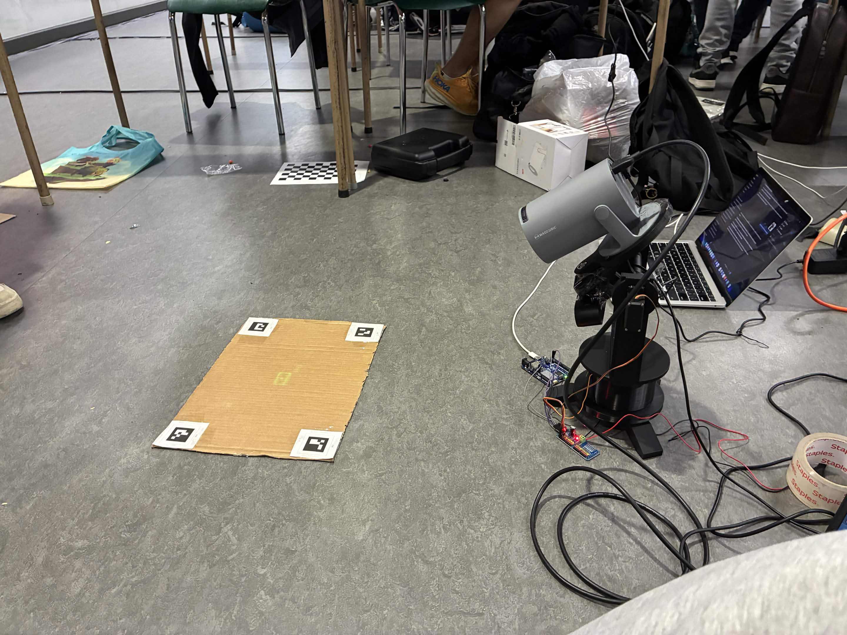
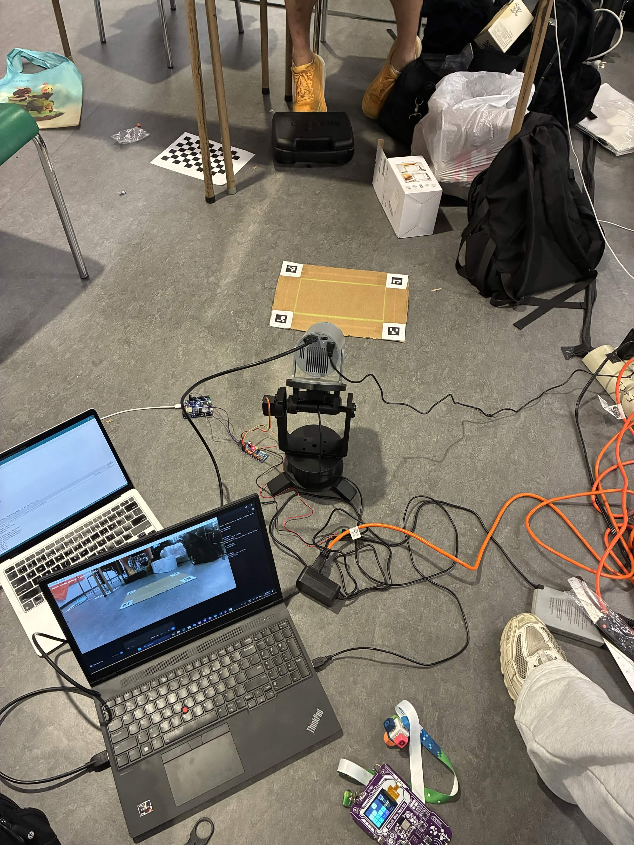
- Projection directly onto the workspace: The next part's footprint is projected directly onto the workspace, showing you exactly where the next piece needs to go.
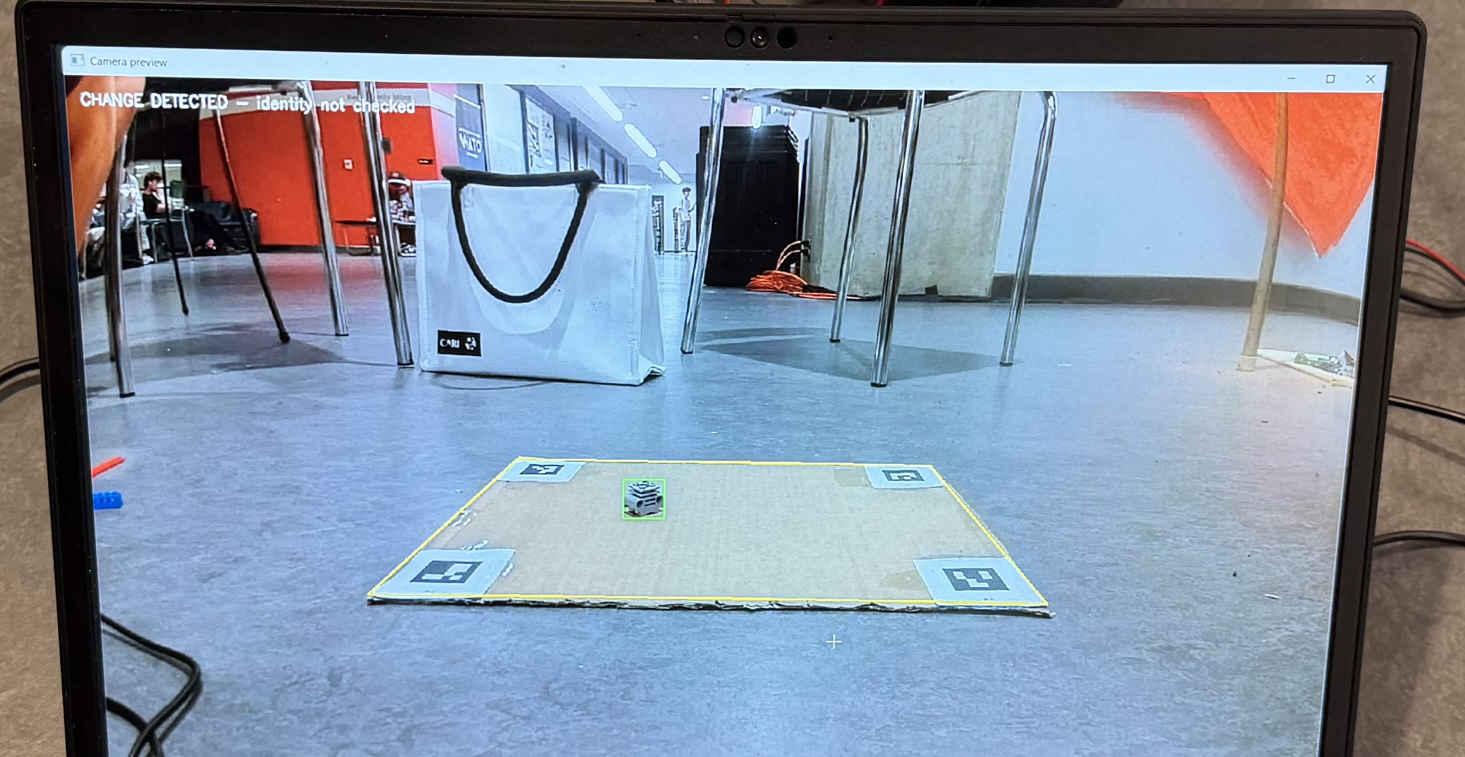
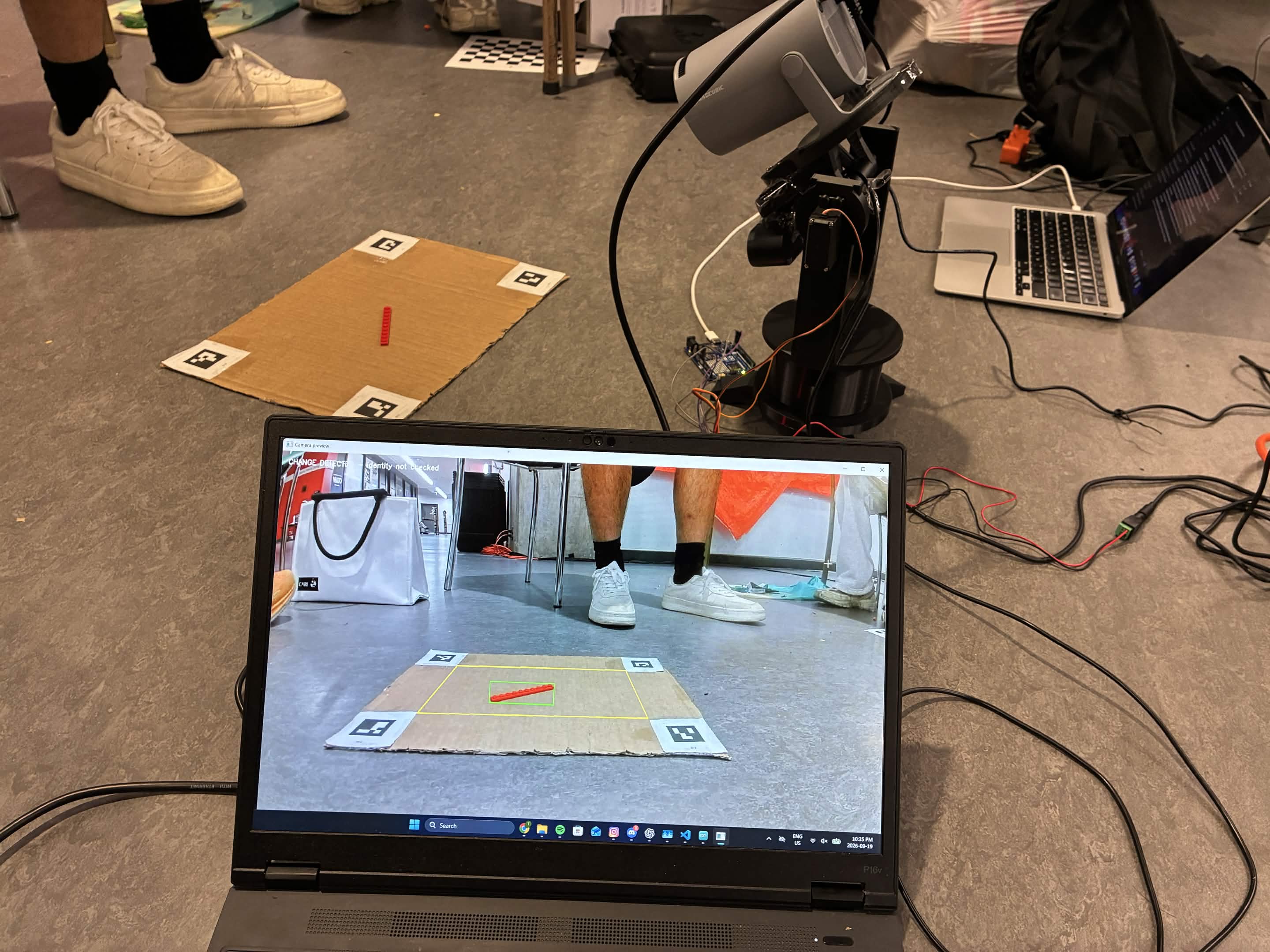
- The camera checks your work. Place a part and Visionary lets you know whether the part is correctly placed.
Between steps you can slide and rotate the workpiece flat across the bench and the guidance follows it-a marker on the moving base re-registers the CAD model to wherever it now sits, so you can turn the build toward you to reach an awkward step.
Instead of machine learning, parts are identified by rendering the CAD mesh's silhouette from the camera's real viewpoint and comparing it to what changed on the bench.
How we built it
Four subsystems, built in parallel by four people.
1 · The rig: A custom mount holds the camera and the projector together above the bench, aimed down at the workspace, with pan/tilt servos driven by an Arduino. This matters more than it sounds because the entire projector calibration is a single fixed transform between the camera and the projector, so if those two ever move relative to each other, every projected target lands in the wrong place. Building a mount that holds that relationship rigid while still pointing both instruments down at a workable angle is what lets the rest of the system operate at all.
2 · The CAD exporter: A Fusion 360 add-in using the Design API. It exports one STL per unique component in component-local coordinates, plus a .json file of the assembly carrying each occurrence's position and rotation, a precedence graph built from interface geometry, and a topologically ordered assembly plan.
3 · Calibration: Camera intrinsics come from 30 chessboard views at 0.4437 px reprojection RMS. The projector is then calibrated as an inverse camera: it projects a known dot grid, the camera finds the dots, and we solve for the projector's own intrinsics plus the rigid camera-to-projector transform (2.479 px RMS). That is what lets us draw a shape in board millimetres and have it land in the right physical place.
4 · Perception: Four fixed 30 mm ArUco markers define the board plane through solvePnP. A fifth marker rides on the movable base. Verification runs as a chain:
- Temporal frame differencing finds where something new appeared — never what it is. The difference blob is contaminated by shadow and projected light, so its shape is untrustworthy even when its location is good.
- Each candidate STL is rendered as a filled-triangle silhouette from the live camera pose, swept through yaw and scored by intersection-over-union. The winner has to clear a floor and beat the runner-up by a margin.
- A metric fit then recovers X, Y and yaw in millimetres at that part's CAD support height, and compares them against the target.
Later steps additionally gate on HSV colour, so a new blue brick is separated from the grey engine block underneath it by hue rather than by luminance alone.
Challenges we ran into
A test suite that failed to catch a few bugs: Our synthetic camera fixture placed the camera below the board plane, which passes every positive-depth check for flat parts, but mirrors every silhouette. The fixture and the code were wrong in the same direction, so they agreed with each other. The fix was a guard that refuses a camera underneath the table, plus a rectification step, and a test that documents the handedness explicitly.
The camera not being overhead: It sits at 20–40° to the workbench, so the raw image foreshortens the board and varies in scale across it. A naive template match compares a part against a squashed, mirrored version of itself. We rectify the board plane before matching, so that in the matching view board +X is right, +Y is down, and pixels-per-millimetre is exact.
The bug that cost us the most time: Stacked parts kept returning UNCERTAIN. We were confident it was occlusion. We measured it: the new part is the frontmost surface almost everywhere, ceiling 0.975–1.000. So we were confident it was height instead. We measured that too: ±5 mm moved the score by less than 0.04. Both hypotheses were wrong.
The actual cause was one line in change detection: max(candidates, key=cv2.contourArea) kept only the largest fragment. When a part overlaps a similarly coloured one, barely any pixels change where they meet, so a single placement reads as two blobs and half of it is silently thrown away. An 8% blind strip dropped the score from 0.819 to 0.418 and collapsed the identification margin from 0.345 to 0.027 — and a margin that small is exactly what "confused" looks like. Merging nearby fragments instead of discarding them fixed it.
Thresholds that measured our rig instead of the truth: The board-drift gate was 1.5 px — 0.68 mm — on a cardboard fixture sitting on a table. And the moving-base check latched on a single frame, so one motion-blurred frame or a hand shadow crossing the marker ended a placement permanently, with no way back.
A camera index: The webcam was device 0 on one laptop and 1 on another. Picking the wrong one produces perfectly plausible geometry computed with the wrong lens calibration, and nothing errors. We now identify the right camera by asking which one can actually see the board markers.
Accomplishments that we're proud of
- It goes end to end. A CAD file in, a verified physical assembly out, with corrections in real millimetres along the way, and no trained model anywhere in the pipeline.
- It is calibrated, not approximated. 0.4437 px camera residual, 2.479 px projector residual, and a measured physical landing error of 1.15–3.41 mm at the board centre.
- The moving base works. You can slide and rotate the workpiece between steps and the guidance follows it, which took a proper rigid-transform chain rather than a homography shortcut.
- We debugged by measurement. Several confident theories were killed by ten-line experiments. Being wrong twice in a row about the stacking bug, quickly and cheaply, was what eventually found the real one-line cause.
What we learned
Frame differencing should localise, never identify. The moment you let the difference blob decide what a thing is, shadows and projector light start voting.
A threshold can end up measuring your rig instead of your correctness. Our absolute silhouette-overlap gate tracked camera elevation more closely than it tracked whether the part was right. The actually informative number was the margin between the best and second-best candidate, so that is what now decides identity, while the absolute score was demoted to a junk filter.
Passing tests are not evidence when the fixture shares the code's assumption. Both have to be wrong in the same direction only once for a whole suite to go green over a real defect.
Measure before theorising. Two separate confident hypotheses, both disproved inside a few minutes by simulation. The instinct to explain is much faster than the instinct to check, and it is wrong more often.
Geometry is unforgiving and completely honest. At 19° of camera elevation, a 2 mm error in assumed part height becomes a 5.8 mm error in measured position. No threshold tuning will ever fix that; the only real fixes are better geometry or a higher camera.
What's next for Visionary
- Occlusion-aware rendering. Compare
render (assembly + new part) - render (assembly)against the real frame difference, instead of matching an isolated mesh. Every accepted part's pose is already known, so the renderer has everything it needs. - Speed. A verification pass takes a few seconds across three parts, and 95% of the points being projected are duplicate STL vertices. Projecting only unique vertices is 25.7 ms → 3.9 ms and bit-identical — roughly a 5× speedup for free.
- Raise the camera, then re-tighten the gates. Several thresholds were loosened to survive a 19° mount. Most of that can be given back from a steeper angle.
- Markers on individual parts for parts large enough to carry one, giving full 6-DoF ground truth in a millisecond instead of a silhouette search — and, just as usefully, a way to measure how accurate the silhouette method really is.
Built With
- aruco
- autodesk-fusion-360
- camera-calibration
- computer-vision
- numpy
- opencv
- photogrammetry
- projection-mapping
- python
- stl


Log in or sign up for Devpost to join the conversation.