-
-
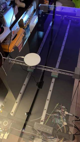
Linear rail and Belt system for the charging pad
-
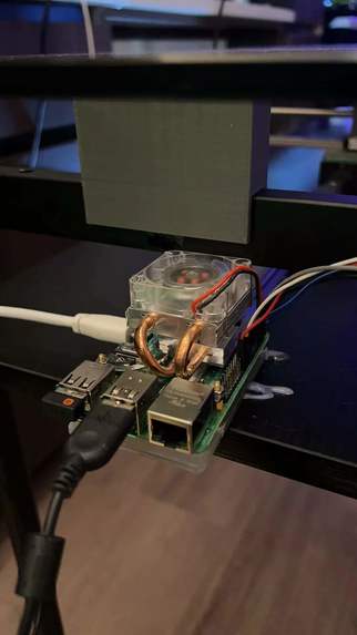
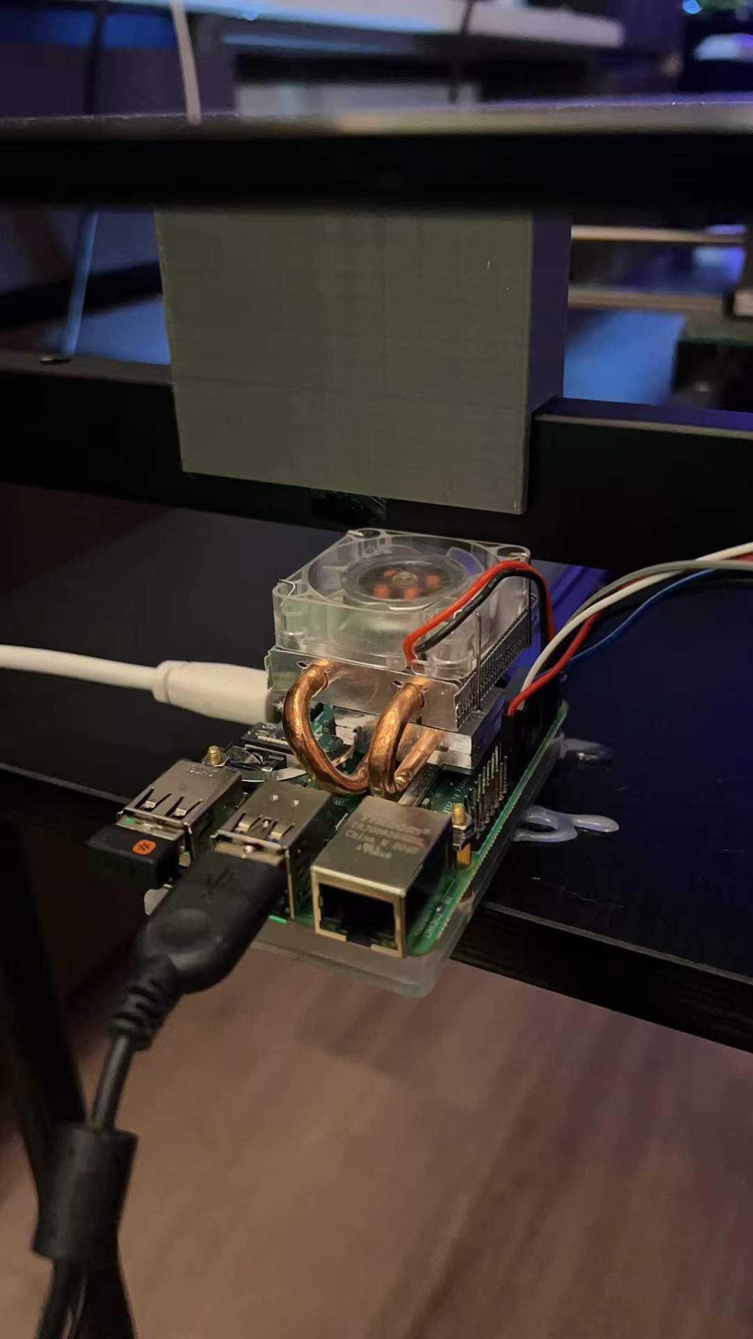
Raspberry Pi 4 for OpenCV
-

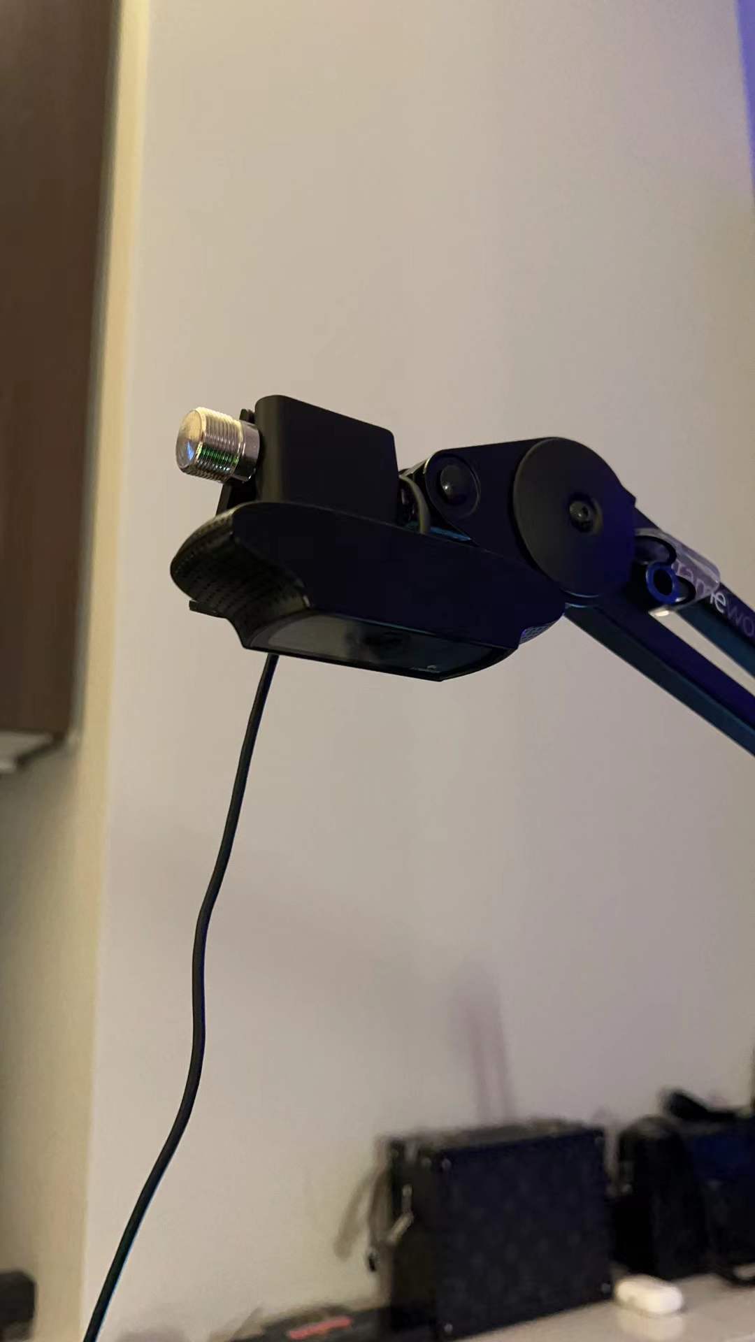
C920 Camera
-
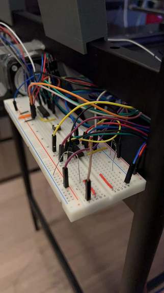
L293D circuits
-
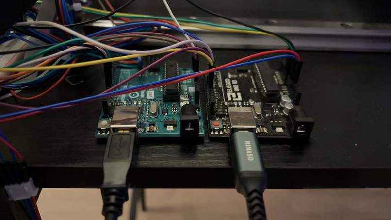
Arduino boards for Stepper motors


Abstract
We decided to design a system that can automatically locate your phone on a surface and the wireless charging base will move to the right position and start charging your phone or another wireless charging device. This could be applied to a bedside table or a working desk. My initial idea is to use Raspberry Pi to support the CV part and generate coordination information for the motor control system, which I prefer to use ATmega328p MCU.
For sensors, we just need a webcam to capture the object on the table surface. we might upgrade the camera to stereotype in order to get more accurate location information. We need two-step motors to drive the linear slide rails. Two sets of linear rails can let the charging pad move across the entire surface. A charging pad that supports the most common fast-charging devices. It might be hard to train the ML module to recognize a smartphone on a messy table and Raspberry pi only supports TensorFlow Lite which the functionality is quite limited. I also need to design a system to collect the free wires flying around two rails, to make sure they won’t entangle. For safety features, I need to put switches that prevent the motors from going too far which might damage the rails or gears.
Motivation
Wireless charging has been widely used on digital devices. Users can just simply put their phone on the charging pad and pick it up when needed without unplugging any cables. But wireless charging has some limitations, the device has to be put right at the center of the charging pad, otherwise, the two coils would not be able to transfer energy. To make our life much easier, we decided to design a desk that the whole surface can act as a charging pad, so users don’t have to worry about where to put the phone. And the same method can be scaled and applied to a bedside table or other surfaces to match any design requirement.
Goals
Two linear rails can drive the wireless charger to the destination
Two motors can move simultaneously
Mount the camera in the right location which included the surface of the desk
Test wireless charging pad and then ensure it can charge through the glass panel
The converting coordinate system correctly represents the device location
The Computer Vision module different devices on the surface
The pad can move to the phone’s converting coordinates and successfully charge the phone
After fully charging the first device, the charging pad can move to the next device
Methodology
Camera + Pi
Use Computer Vision to locate the device Ran OpenCV on raspberry pi with coco database(More detailed information in Appendix A) to achieve locating phones on the desk surface.
Convert the location information to the preset coordinate system
Trained coco dataset with OpenCV. Code attached in Appendix A. The official detection model from the COCO dataset could detect phones but in our case, we need a model that provides more accurate detection so we took 150 photos of the iPhone in different angles and light conditions. Which as shown in the image above, could successfully detect multiple phones on the desk surface.
Drive the step motors
At first, we bought a V1 motor shield for the Arduino board, but then we figured out it failed to drive two NEMA 17 stepper motors even with an extra power supply enabled. However, by learning from the board, we found out the L293D is the chip that we were looking for, so we directly took it from the board and mounted it on the breadboard which gave us more flexibility and more functionality compared to the original setup.
We used two ATmega328p MCUs to drive two stepper motors. And two L293D motor control chips. The L293D is an IC with two H-Bridges, and each H-Bridge will drive one of the electromagnetic coils of a stepper motor. By energizing these electromagnetic coils in a specific sequence, the shaft of a stepper can be moved forward or backward precisely in small steps. Before we start hooking the motor up with the chip, you will need to determine the A+, A-, B+, and B- wires on the motor you plan to use. The best way to do this is to check the datasheet of the motor. For our motor, these are red, green, blue, and yellow.
We tried a lot of different speed tests for our motors since we changed one of the Linear slides to Belt driven system, so the ratio of moving is changed by the step size of the end wheel on both ends of the belt.
Another extra problem we encountered was the same ground was shared between the two boards. Though we gained the benefits of better stability for driving two stepper motors at the same time, as we used our hand to scroll the rail to move the mounting block to the initial position, we figured out that the other Arduino board’s LED indicator lit up even without the power being turned on.
As a result, we tried different approaches to avoid this problem because it will not only interface our ADC reading but also will make the other motor move weirdly. The approaches included using a capacitor, transistor bridge, huge metal block, or diodes on both VCCs and GNDs. In the end, we found with the limited electronics parts we had the best way is to use the diode on the shared ground for better space management and less complexity when we need to debug the circuits.
Linear Slides/Belt + Step motor
Create two linear slides system
We used two sets of linear sliders/rails. The horizontal rail is built by two linear slides and a belt that’s driven by a stepper motor. The vertical rail is a linear screw rail. The two slides/rail can go through the entire surface of the desk.
Set start/stop point on slides
For this project, we still have to manually adjust the charging pad at the center of the table each time it restarts. We tried to add self-alignment into our project so that it can automatically go to an initial position. But that function caused us a lot of problems since the stepper motors are not stable, sometimes it just randomly runs out of the rail and all positioning information had to be reset.
Push charging pad to the desired location
The method we use to let the pi and UNO board communicate with each other is, we first enabled GPIO pins on the pi and when it gets the location of the phone, it computes the distance that the charging pad has to travel in X/Y direction and convert it into a short HIGH signal on corresponding pins and let ATmega328p measure how long is that HIGH signal then converts it to steps for each motor to travel. Since the output voltage of the pi is 3.3v we had to use a logic level shifter to get a 5v signal. Reset after charging finished
We achieved this part with a tricky method. The charging pad we used for this project was bought from amazon and it has LED lights that indicate the charging status. When it’s green, it means the charging is in process and when it finishes charging, it turns off. So we wired that LED to the pi’s GPIO pins and let pi detect voltage change on the LED. So that our code would know if one device has been fully charged or removed from the charging pad.
Challenges we ran into
We designed about 6 different 3D prints parts to support the project, some are used for mounting the block of the rail, some are used for support the glass panel, and some are used for holding the Stepper motors. Though our parts came out in good shape in the final stage we spent several days printing them and because of the quality of the printer, and some unfamiliar settings we had, we had so many failed PLA models that are much below our expectations. So it's always important to test the printer and see what's the best setting for the designed parts.
Results
Our project could successfully locate phones on the table and drive the charging pad to the desired location to charge the phones. When pi detects a phone on the desk, it starts counting how long the phone remains at the same spot. Over 3s without significant displacement, the Pi will compute the X/Y displacement for the charging pad to move and send HIGH states to corresponding pins. The ATmega328p receives HIGH and triggers the timer to count how long the HIGH signal is, then convert the signal into steps to drive the motors.
We successfully achieved all the topics on the ‘goals’ part. Though we got a lot of comments from the proposal part about if we will finish the project with such an amount of time due to the complexity, the result came out better than what we expected from the beginning because the detecting speed from the computer vision module and the moving speed from the linear rails/belt system is more precise and faster than we thought.
Conclusion
During the project, we got more familiar with ATmega328p development and tried to let different MCUs communicate with each other. The process of generating object detection was a pain but the result turned out good enough to achieve our needs.
We learned the basics behind object detection, how stepper motors work and how precise the linear screw rails could achieve. The belt-based rail could achieve our needs but compared to the screw rail, it is sometimes stuck and one or two steps would be missing, in our case, it’s not a big deal but if we bring it to a smaller scale, precision becomes more important. We first decided to use two screw rails, but a 1000mm screw rod with a specific screw pitch lead is so pricey and takes a long time to make.
For a more smooth movement of the charging pad, we could add two more stepper motors and place the 4 motors on each corner so there won’t be a motor moving around the table, the height can be reduced down about 5-10cm. The next step could be adding IoT functionalities to our project. For example, a real-time weather display and ToDo list can be edited by the user via phone. Users can interact with the desk by hand signs or touch.
What's next for THE DESK
Implement with some cool IoT functions Print some useful information on the LCD screen
References
Object detection: https://cocodataset.org/#download –COCO dataset https://www.youtube.com/watch?v=HXDD7-EnGBY –Object detection on Pi https://towardsdatascience.com/how-to-work-with-object-detection-datasets-in-coco-format-9bf4fb5848a4 –Train COCO detection model
Stepper motor: https://www.youtube.com/watch?v=rE6ZgBLFCFw –L293D stepper motor driver
Built With
- arduino
- atmel
- c
- python
- raspberry-pi
- tensorflow


Log in or sign up for Devpost to join the conversation.