-
-
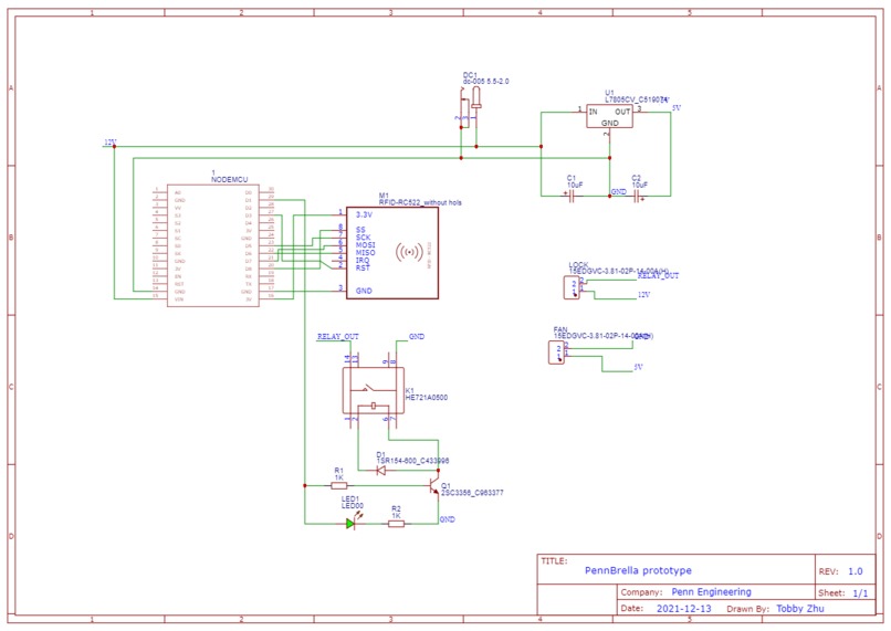
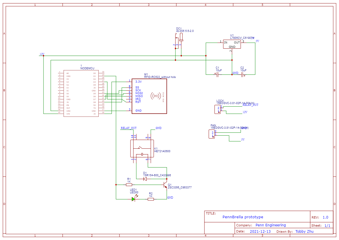
Circuit Schematic
-
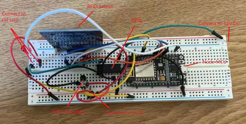
Breadboard
-
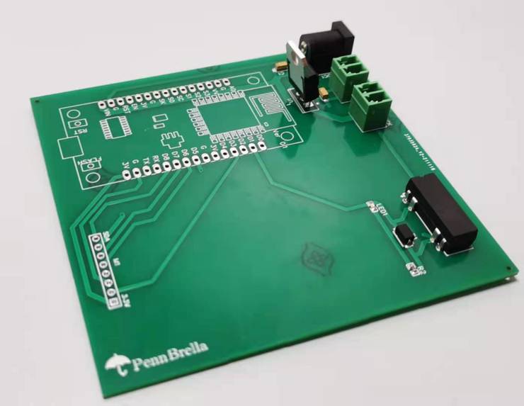
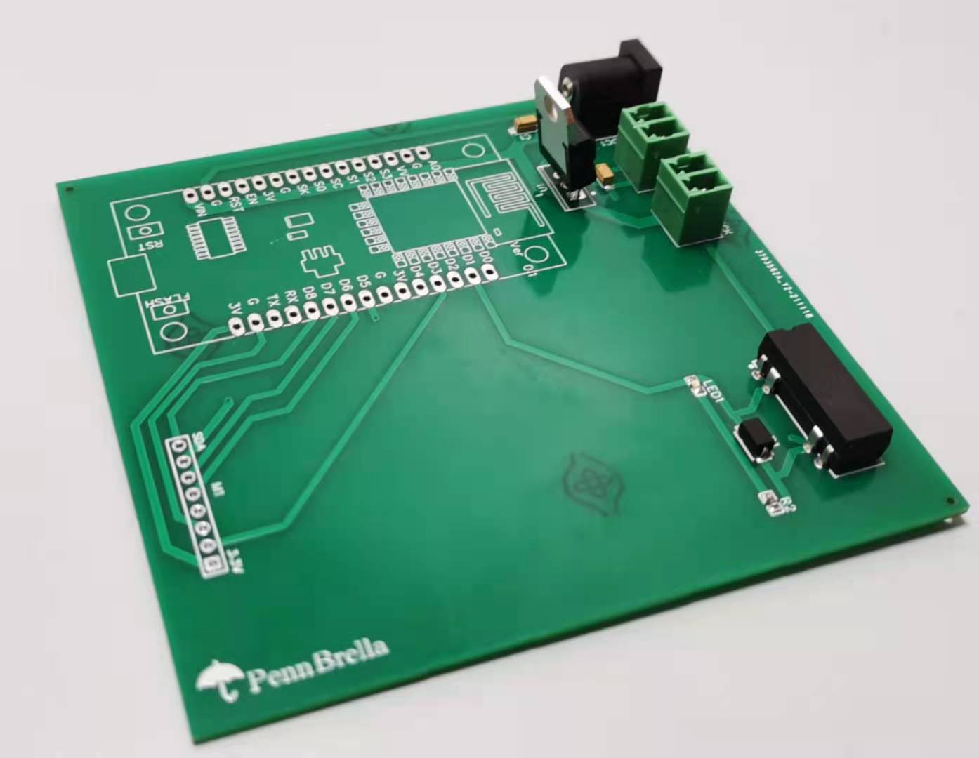
PCB
-
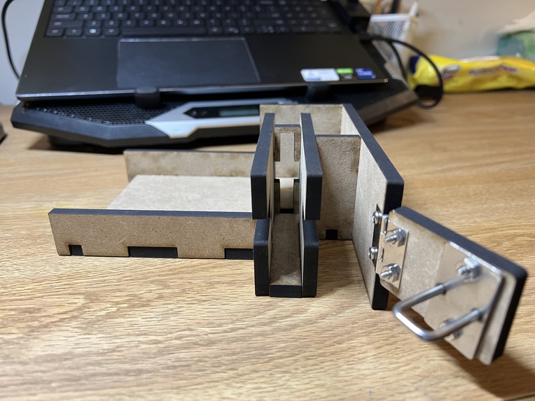
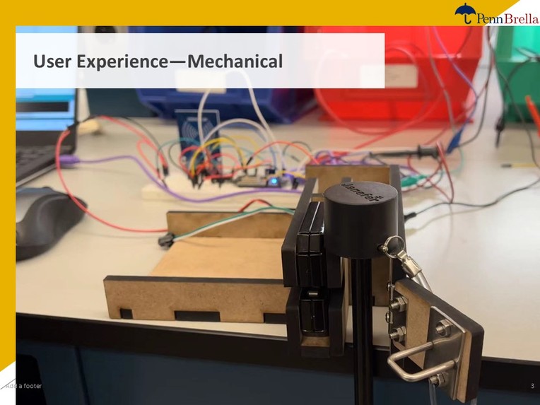
Mechanical Lock
-

Presentation Slide 1
-
Presentation Slide 2
-

Presentation Slide 3
-
Presentation Slide 4
-
Presentation Slide 5
-

Presentation Slide 6


Inspiration
Philadelphia features unpredictable yet heavy rains, wetting innocent class goers as they wander around Penn's campus. But carrying an umbrella at all times is awfully inconvenient. Inspired by shared public bicycle systems such as Indigo, we created the shared umbrella system for Penn's campus, which we proudly named PennBrella. The system comprises of umbrella stations in Penn buildings, where students can borrow an umbrella with a tap of Penn Card and return it to any station in their convenience.
What it does
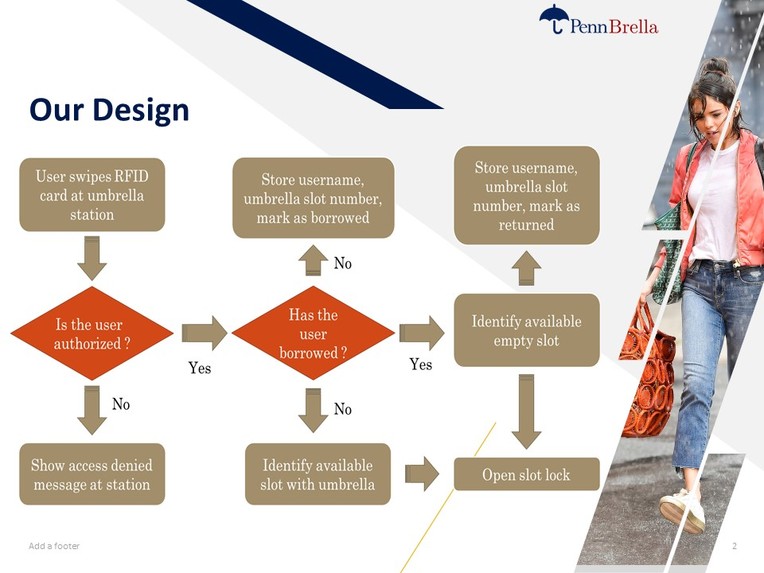
The system reads a touchless card through a RFID reader and logs the cardholder's information to cloud. If the user is authorized, it unlocks the umbrella locker to allow the user to borrow/return an umbrella, before changing the borrow status of the user and upload it to cloud.
Hardware and software breakdown
In its ultimate design, each PennBrella locker unit consists of a micro-controller, a Wi-Fi module, an RFID reader, an indicator light or screen, and an electromagnetic lock. In our current prototype, all computation and Wi-Fi communication are done using a Node MCU, which is wirelessly connected to a Wi-Fi network, and physically connected to a RC522 RFID reader, the electromagnetic lock, and a LED.

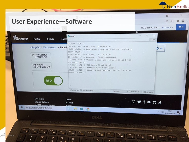
When the power is on, the RFID reader continuously detects RFID cards, and sends the card’s ID to Node MCU as soon as a card is detected. The code uploaded to the MCU then prints the card ID, uploads it to cloud (Adafruit IO), and determines whether the card is authorized.
// Look for new cards
   if ( ! mfrc522.PICC_IsNewCardPresent())
    return;

// Select one of the cards
  if ( ! mfrc522.PICC_ReadCardSerial())
    return;

  //Show UID on serial monitor
  Serial.print("UID tag :");
  String content= "";
  byte letter;
  for (byte i = 0; i < mfrc522.uid.size; i++)
  {
     Serial.print(mfrc522.uid.uidByte[i] < 0x10 ? " 0" : " ");
     Serial.print(mfrc522.uid.uidByte[i], HEX);
     content.concat(String(mfrc522.uid.uidByte[i] < 0x10 ? " 0" : " "));
     content.concat(String(mfrc522.uid.uidByte[i], HEX));
  }

String card_username=content.substring(1);
username->save(card_username);
If the card ID is in the list of authorized users, the system then reads the borrow status of the user from Adafruit IO. If the status shows the user has borrowed an umbrella before this tap, then the system changes the status to “returned”, and sends a 100 ms HIGH output pulse through NodeMCU to unlock the lock. On the other hand, if the user has returned his previous umbrella, the system recognizes that he is attempting to borrow an umbrella, and thus marks his status to “borrowed”, before unlocking the lock.
if (card_username == UID) {
    Serial.println("Card recognized");
    if (!borrowStatus) {
      borrowStatus=1;
      Serial.print("Umbrella borrowed for user ");
      Serial.println(card_username);
      borrow_status->save("Borrowed");
      delay(300);
      digitalWrite(LOCK_PIN, HIGH);
      delay(100);
      digitalWrite(LOCK_PIN, LOW);
    }
    else {
      borrowStatus=0;
      Serial.print("Umbrella returned for user ");
      Serial.println(card_username);
      borrow_status->save("Returned");
      delay(300);
      digitalWrite(LOCK_PIN, HIGH);
      delay(100);
      digitalWrite(LOCK_PIN, LOW);
    }
    Serial.println();
    delay(2000);
  }

 else   {
    Serial.println("Card unrecognized - Please try again");
    borrow_status->save("Not Authorized");
    delay(2000);
  }
However, the digital output from Node MCU does not have enough voltage or power to unlock the electromagnetic lock. Therefore, we make use of an NPN transistor connected to both the Node MCU output and a 5V power line to turn this logical output to 5V. The 5V output is then fed into a 5V relay, the switch side of which is connected to another 12V power line. Hence when the output from the Node MCU is a 3.3V HIGH, both the transistor and the relay turn on, and the electromagnetic lock gets a 12V power supply to unlock itself. (See schematic below)

Additionally, a physical LED light receives a signal from the Node MCU and displays the borrow status of the station, with green meaning “ready to borrow” and red referring to an empty lock station. In our future product, the entire circuit will be powered by a 12V DC external source, which is used to power the electromagnetic lock while also stepped down to 5V by a regulator to power the Node MCU. All components except the lock will be integrated onto a single PCB, which is conveniently placed next to the lock cabinet and has easy cable access to the exterior power source.
Future Plans
We plan to construct the physical structure in a modular way and use a PCB-based design to simplify the hardware. This will ensure that our electrical components are packaged in a space-saving, integrated way. Moreover, using a modular method, each part can be replaced easily, and the whole system could be still working while we replace some broken parts.


Log in or sign up for Devpost to join the conversation.