-
-
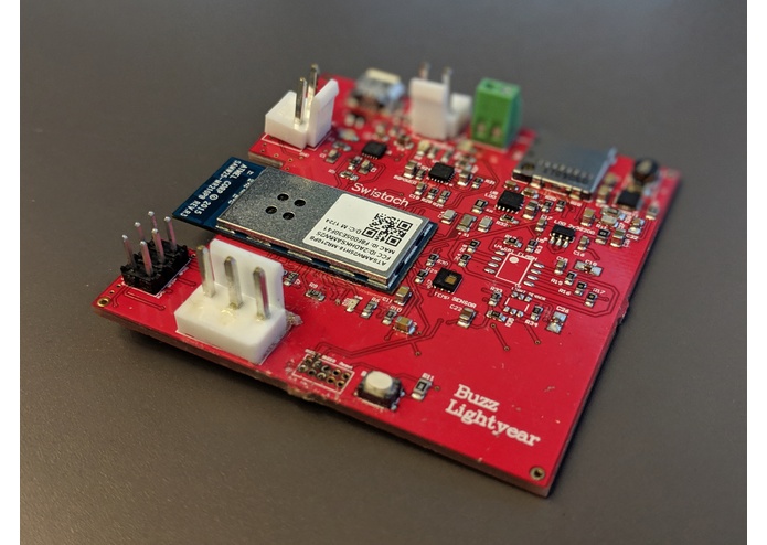
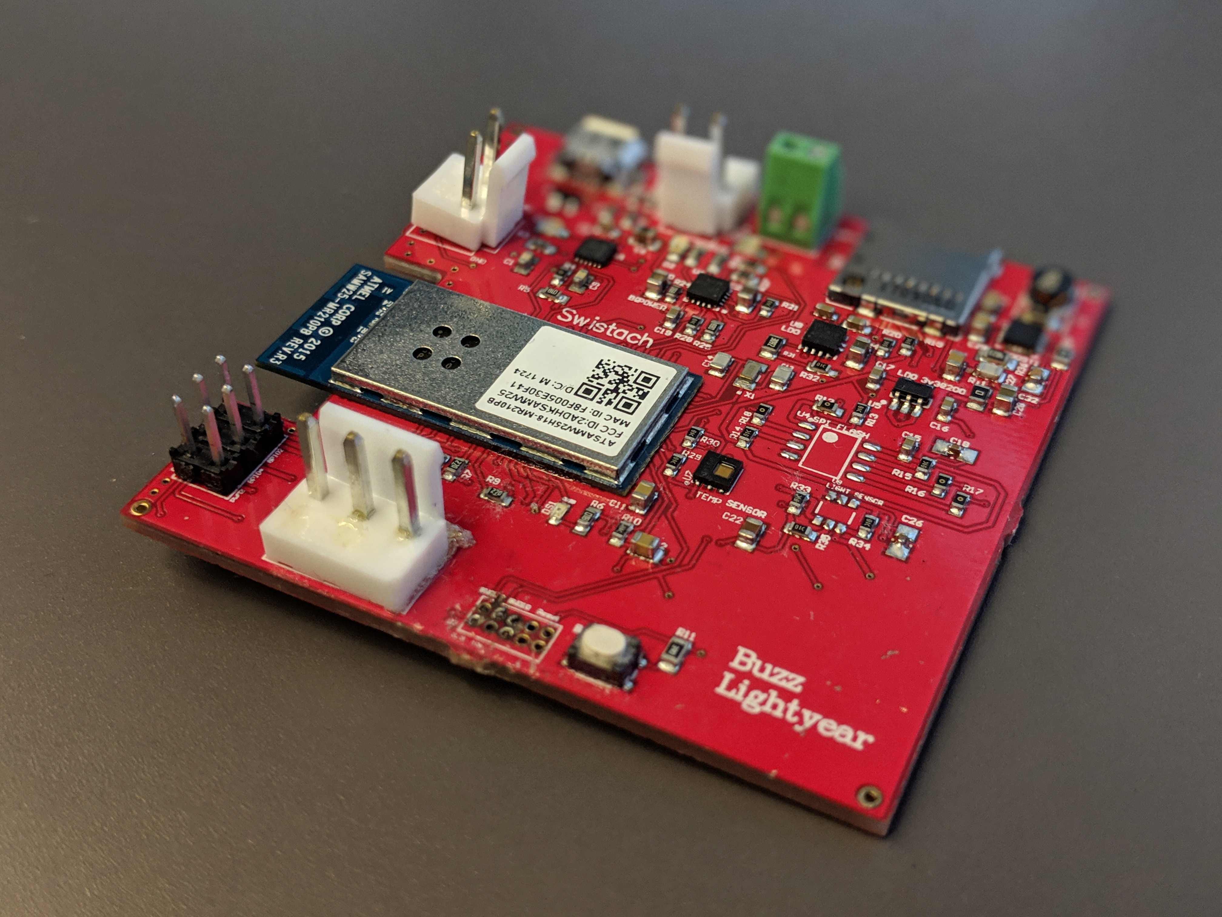
PCB manufactured
-
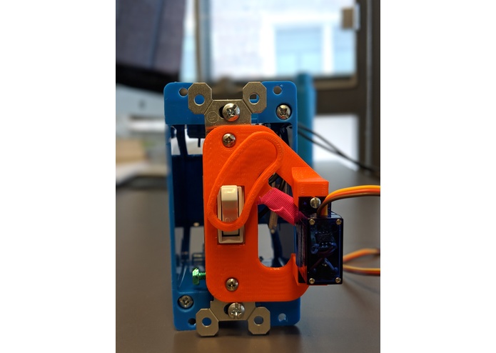
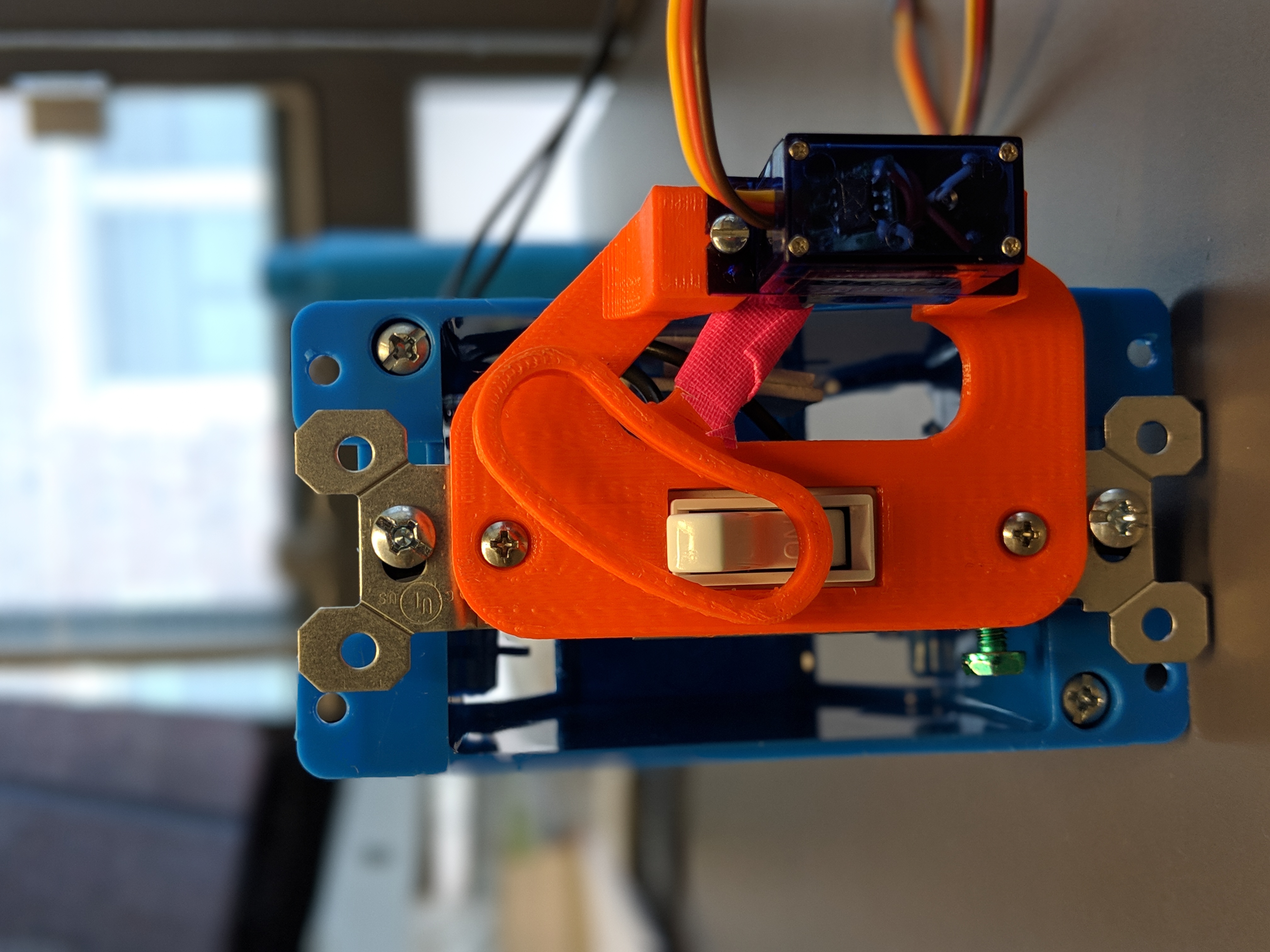
3D printed attachment which goes on the switch
-
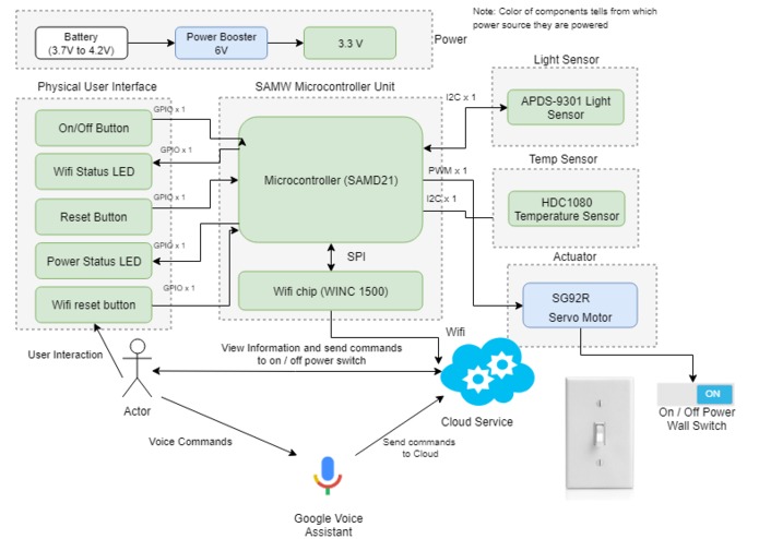
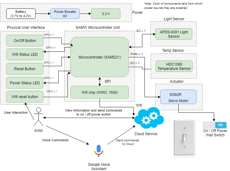
Detailed product diagram
-
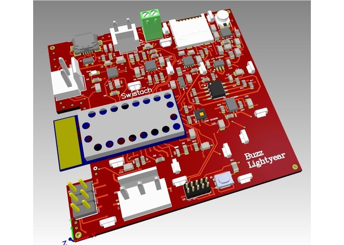
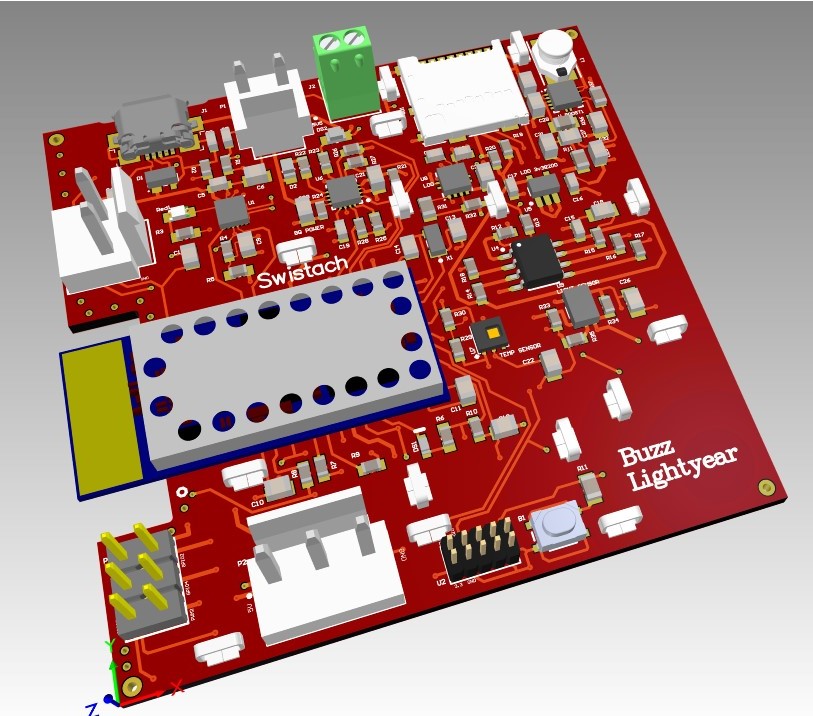
PCB 3D Layout
-
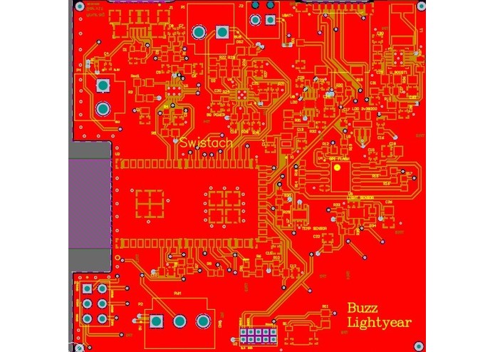
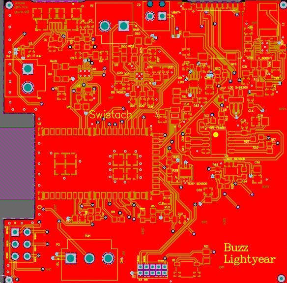
PCB Layout
-
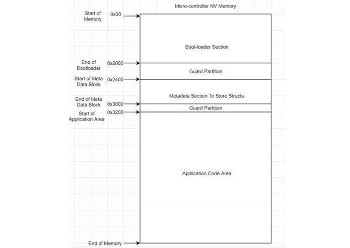
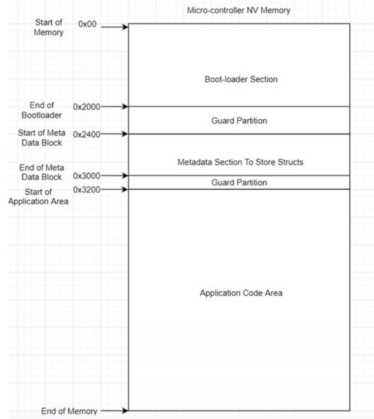
Memory Map of Device
-
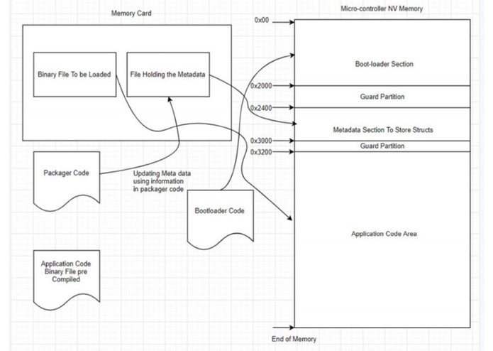
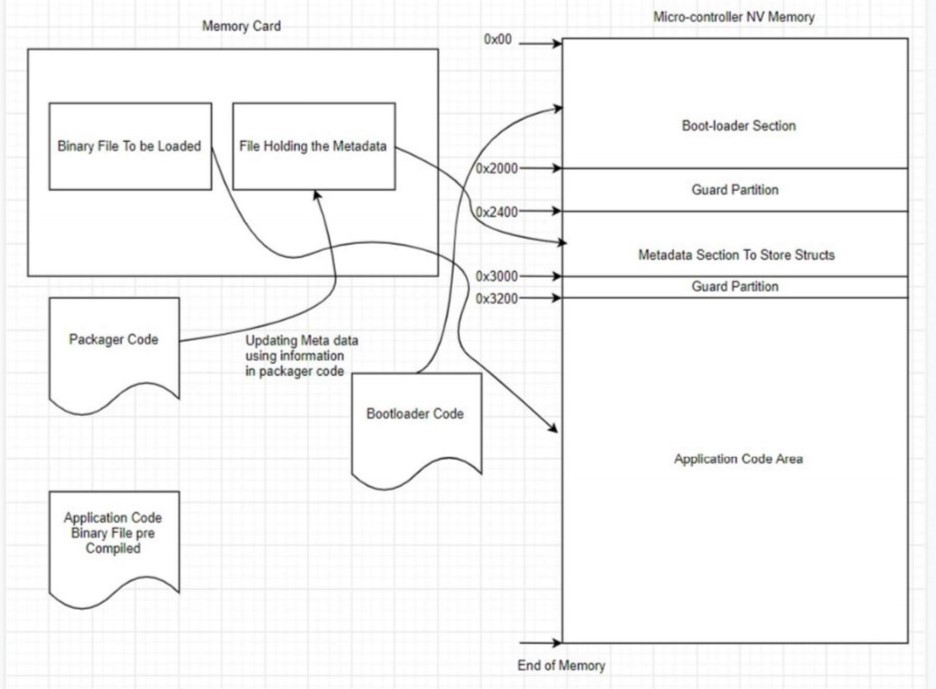
Bootloader Interaction with SD card and NVM
-
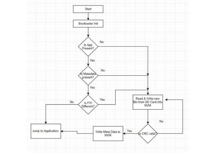
Bootloader Code Flow Chart
-
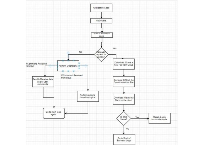
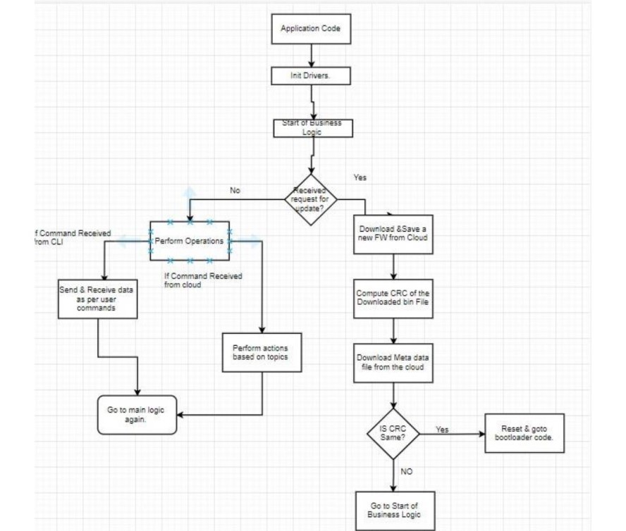
Application Code Flow Chart

Inspiration
We all have faced the problem of going towards the switches in our houses either to On or Off them and it is irritating the most when you are about to sleep, and you have to get up you’re your cozy bed and switch off the light switch. The solution to this is smarter switches, but these switches are expensive, and most people don’t even want to change their existing switches. So, our aim to solve this basic problem by making your existing switch smart without even touching any existing wires or switches using IoT, keeping intact the manual operation.
What it does
The idea is to create an IoT device which can be retro-fitted on top of existing switches and give the capability of controlling them remotely over the internet. The end user can control it using an app, webpage or even through voice commands using Google Assitant like “Hey, Google, Switch on the lights” or “Hey Google, Switch off the light”. This brings in whole new possibilities of making the existing switches simple and smarter. You can control it from wherever you want like switching off light from office if you forgot to, set timers for light to automatically switch ON or OFF, push data to cloud to analyze for how much time the light was ON/OFF. Swistach will never make you walk into a dark room because it will know when you are home. In addition to it, it will also have light sensor which will automatically detect ambient lighting in the room and on/off switch automatically. So, the device can be used in both manual and automatic mode through over the air commands.
Features
- Ambient Light detection to trigger switches automatically.
- Real-time temperature monitoring.
- Google assistant integration for ease of access.
- Over the air Firmware Update.
- Command line interface.
How we built it
Hardware
Components
- Microchip ATSAMW25 (MCU + Wifi) :
- HDC1080 - I2C based Temperature sensor
- APDS-9301 - I2C based ambient light detection
- TGR-92 - Servo Motor
Software
Our solution contains 3 projects; 1) Bootloader Project 2) Application Project 3) Packager Project The following steps need to be followed to run the application a. Modify the package editor code to set the required new firmware version. Run the code in the MCU with SD card connected. This will update the firmware version in the metadata file in SD card b. Now, Compile the Application Project and generate the binary Files. Copy the binary to the SD card directly from the PC. c. Put back the SD card back to be attached to the MCU. d. Run the Bootloader code. Bootloader code decides if the Metadata and application code needs to be copied from the SD card into the VN Memory.
Bootloader Design

The bootloader is entered only when the version of the application code and the version of the firmware in the SD card are not the same. Based on this fact, there are primarily 3 possible cases in which the boot-loader will be accessed;
1) When there is no Application code in the non-volatile memory – The bootloader code first checks if there is any application code present in the memory; if there is no code present, then the bootloader section is entered, and a new firmware is copied in the NV memory.
2) If from above step, we find out that the memory does have an application code, then the bootloader goes and checks the Metadata block of the NV memory. If the metadata block is empty, then the bootloader enters the boot-loading section and copies the new application code and writes the metadata block in the NV memory.
3) If both the application code and the metadata are present in the NV memory, then the bootloader reads the metadata block of the memory and gets the firmware version of the currently running application code. After this step, this retrieved firmware version is compared with the firmware version from the SD card. If there is a mismatch in the version numbers, then the new application code is written in the application code section of the memory. Subsequently, after successful write of the application code, the metadata section of the memory is updated with new values of size, firmware version. The following error cases have been handled in the code;
1) Memory Corruption – The bootloader code checks for corruption of data while reading and writing the binary file from the SD card to the NV memory. A 32-bit polynomial based CRC is computed when the binary file is read from the SD card into the code. After writing the binary file to the NV memory, the CRC is again calculated on the data which is written to the memory. If the 2 values of CRC do not match, then the entire read and write process of the binary file is executed again. We continue this till a good write of the binary file is confirmed.
2) Power Outage – There are multiple key points in the bootloader at which a power outage can prove to be troublesome and brick the micro-controller. To understand how we overcome this issue, let us first look at the key points in the bootloader code and then see how power outage issues are avoided; a. Checking if Application code is present. b. Checking if metadata is present. c. Comparing the firmware versions from SD card and the currently running application code. d. Reading Binary file from the SD card. e. Writing the binary file to the NV memory. f. Validating CRC. g. Updating the metadata in the NV memory.
A power outage at any point is overcome by simply updating the metadata block in the NV memory as the last step in the bootloader code just before jumping to the application code. If during any other process during the boot-loading operation, if the power goes out, the metadata block is not updated at all and is still the same as the old metadata with the old firmware version. So, the next time the micro-controller starts, it checks and finds out there is a mismatch in the firmware versions
and attempts to copy the binary file again. This approach takes care of all the scenarios like partial read, partial write, or any other failure scenario. There will be redundancy of double write when there is a power outage between steps f and g mentioned above i.e. after a successful CRC validation and before writing the metadata block. Detailed memory map diagrams and flowcharts have been added to the image section of dev post.
Application Project
The application project contains the main business logic of the project. After the basic system initialization, the device connects itself to the internet and starts publishing the device statistics like temperature, the button state and heart beat signals to the MQTT cloud. The device also listens to the commands from the MQTT server for either changing the position of the switch or do a firmware update over the air. The application code provides serial interface to the end user or the operator to see and control the device using the Command Line interface. The user can get the health of the device or other important parameters of the device using the in built commands designed. The temperature and the light sensors were interfaced using the the I2C lines to read the sensor values. The temperature sensor returns the sensor value in 14 bit format and needs to be processed for calculating the final temperature value. The output servo motor, which controls the toggling of the switch is interfaced using a PWM module. Pulses of different width but with the same frequency are used to control the direction of the servo motor rotation. A timer program is used to send the data to the cloud periodically every 5 secs.
More detailed flow diagram of the application code has been added in the images section of the dev post.
Update Packager
The update packager project is used to generate the meta data files which need to be uploaded to the server. We have this project to make everything convenient for managing the bootloader and application code projects within the solution.
Challenges we ran into
Board Bring Up
We faced challenges while doing the firmware update on our custom PCB. We had to modify the update script bat file and get the update script to work. The modifications were made to make the script work with the Atmel ICE debugger.
Wifi Connectivity
The issues while connecting WiFi were hard to debug. We eventually figured out that the WiFi was drawing a lot of current from the USB and the micro controller was reset because of Brown Out Reset. To overcome this, we used an external power supply which was capable of delivering this high current demand.
SD Card
On our custom board, we had to modify the SD card library to make it compatible with our custom board.
Accomplishments that we're proud of
- Completing the entire project on our custom board.
- Google Assistant Integration
- Designing our own board from scratch.
What we learned
- Product design
- Component selection
- Altium Designer
- Node Red
What's next for Swistach
From here, we would first fix the power circuit design for our board so that we can get it to work without an external power supply. We would like to set up triggers based on temperature of the room to trigger the switch movement. Change the servo actuator to something which can provide both rotational and linear movement, with this our device can be attached on any type of switch.

Log in or sign up for Devpost to join the conversation.