-
-

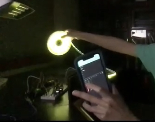
LED Strip colors changed by Blynk App
-
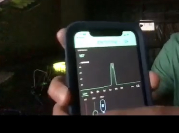
Blynk App
-
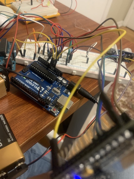
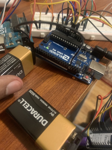
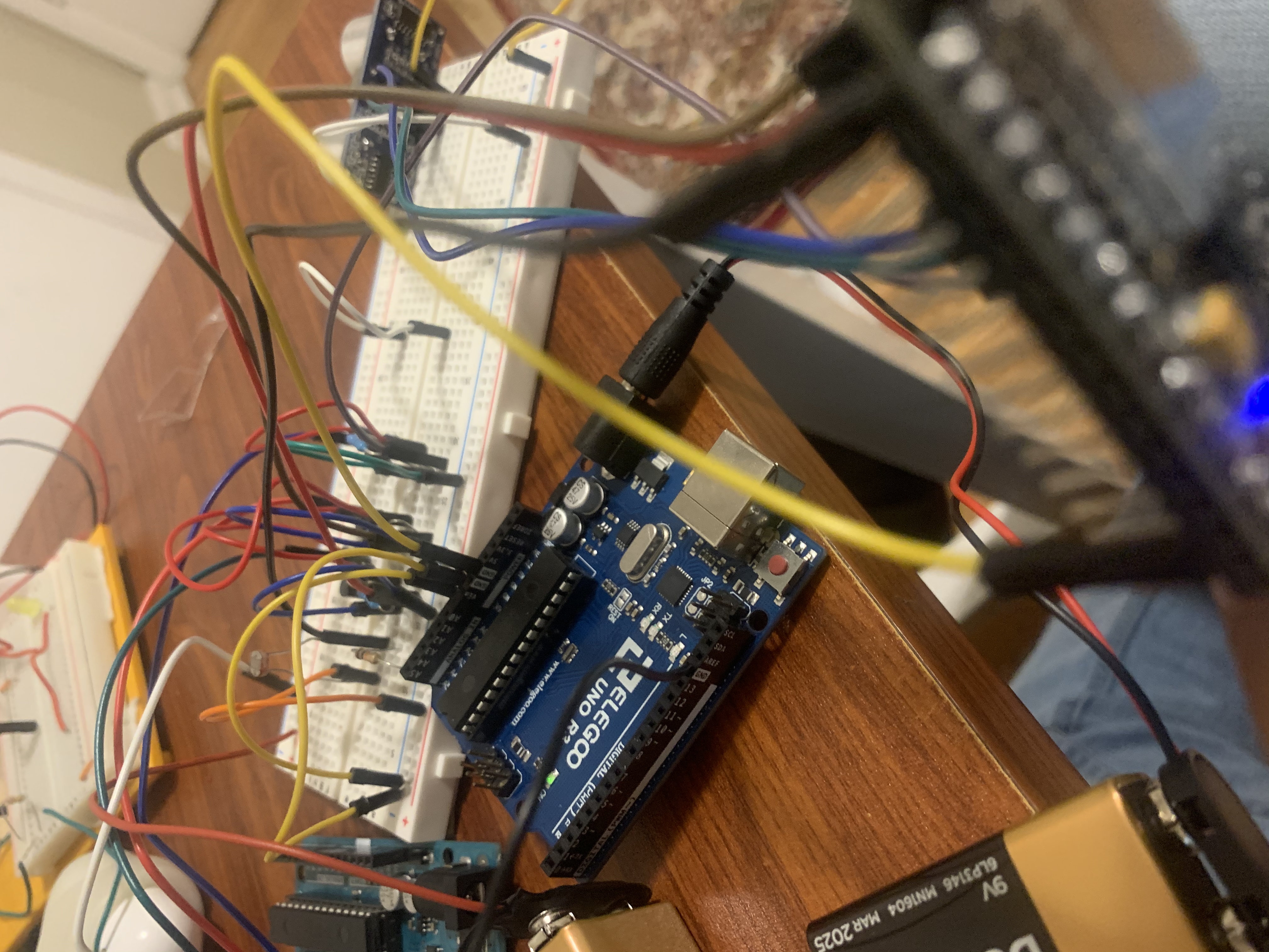
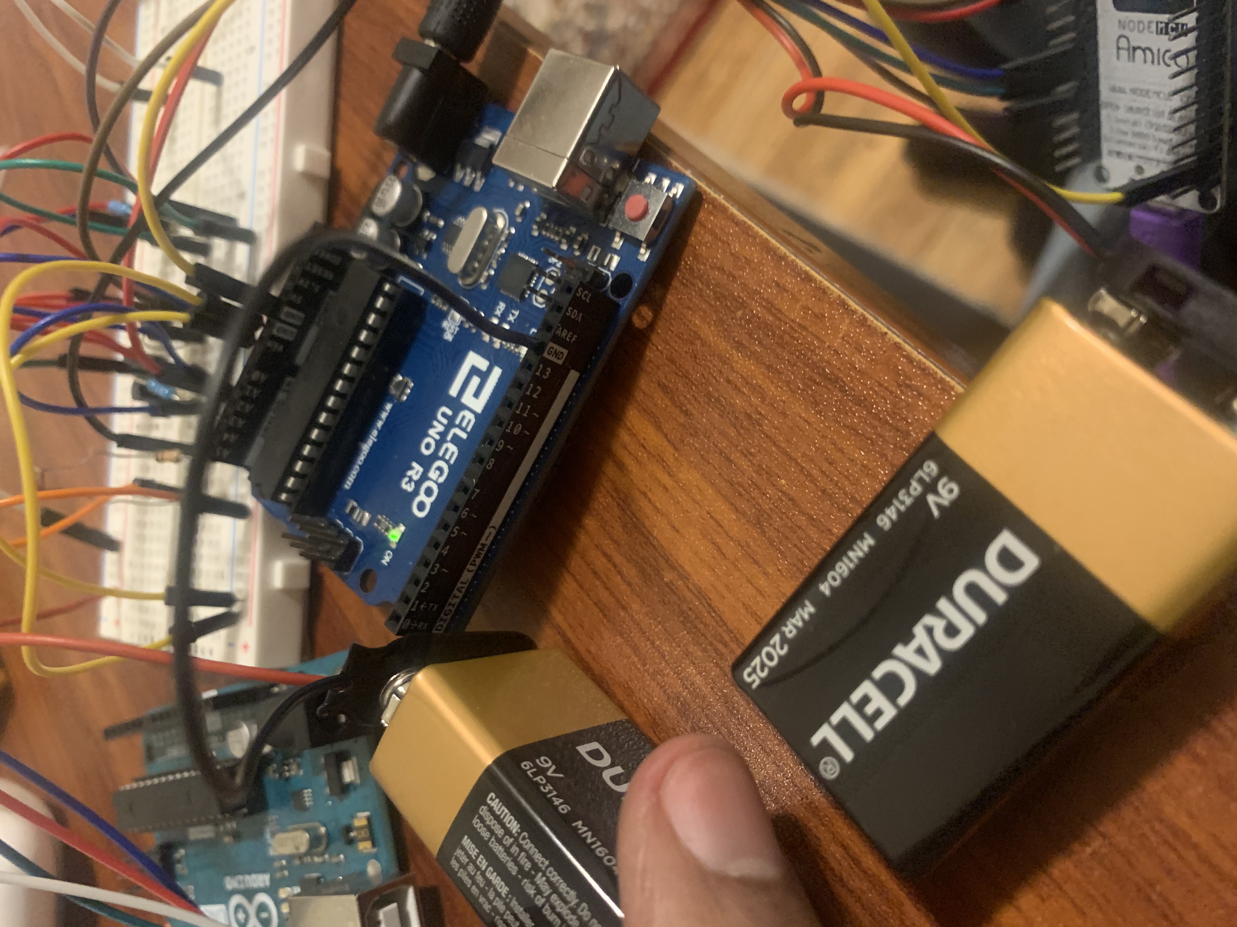
Arduino Board
-
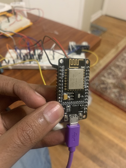
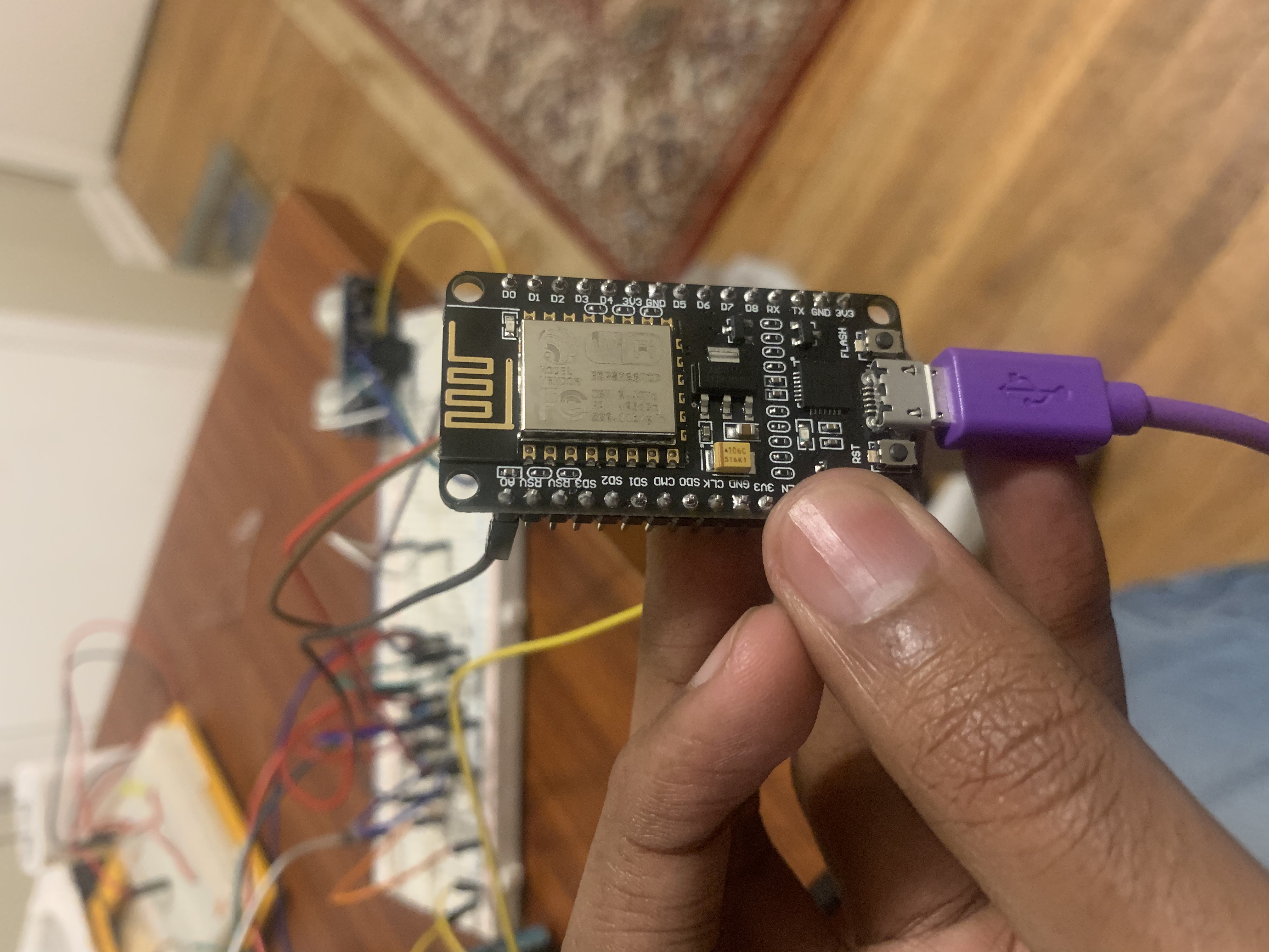
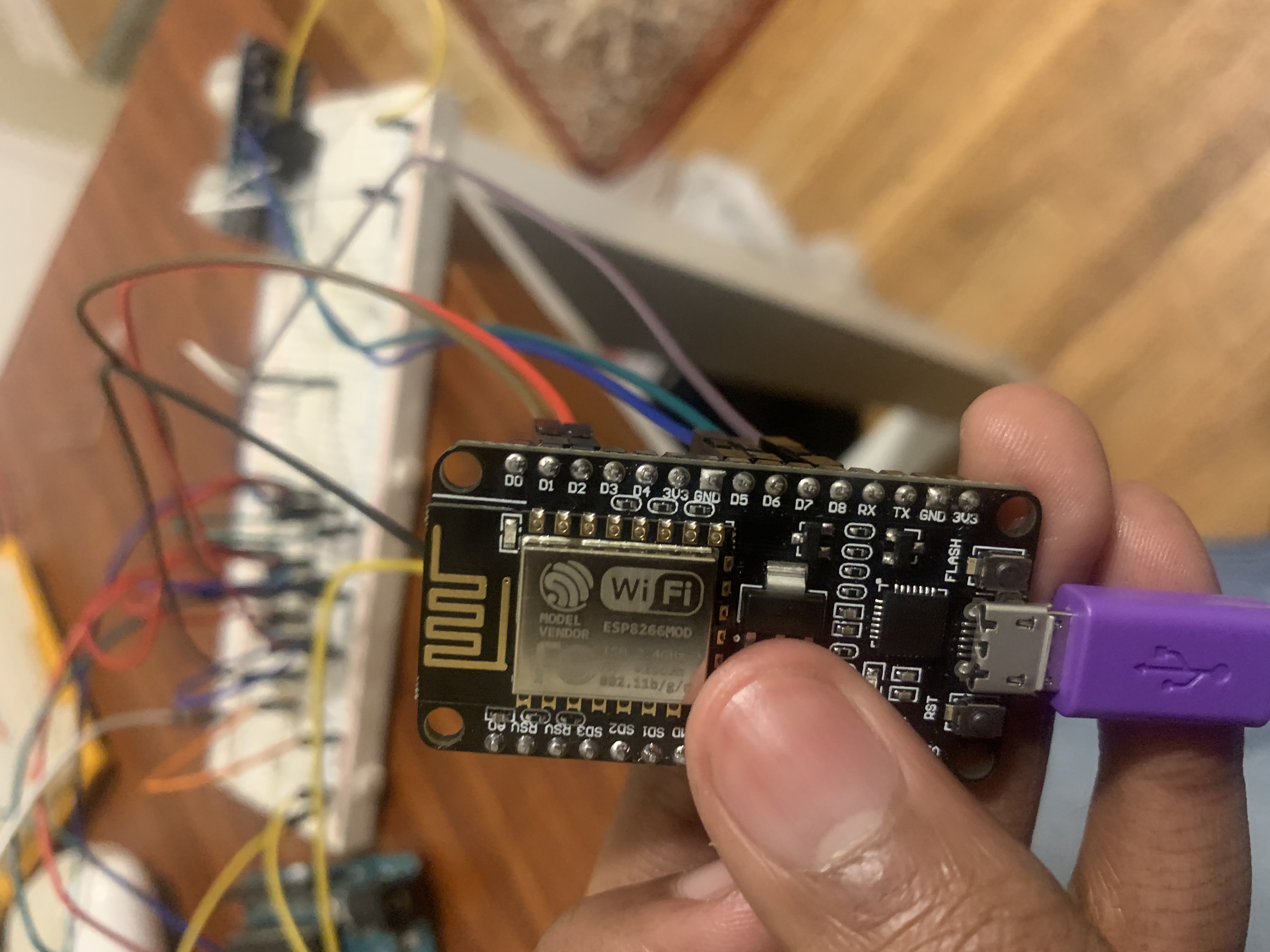
NodeMCU
-
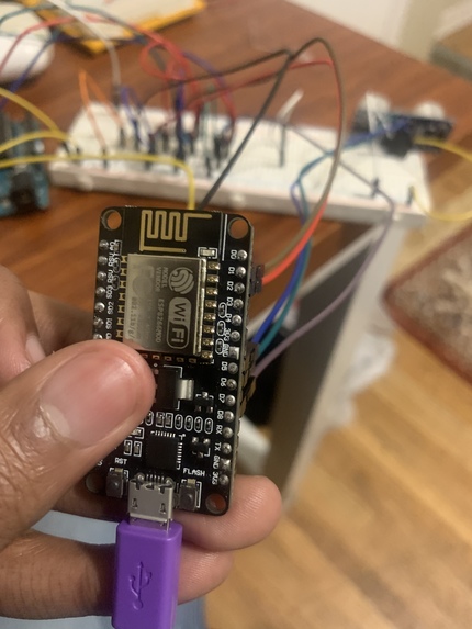
NodeMCU
-
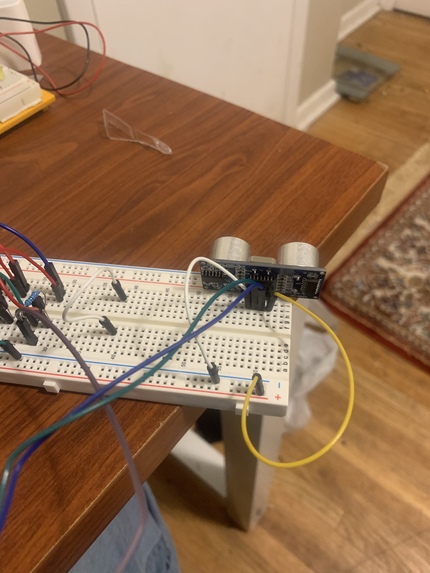
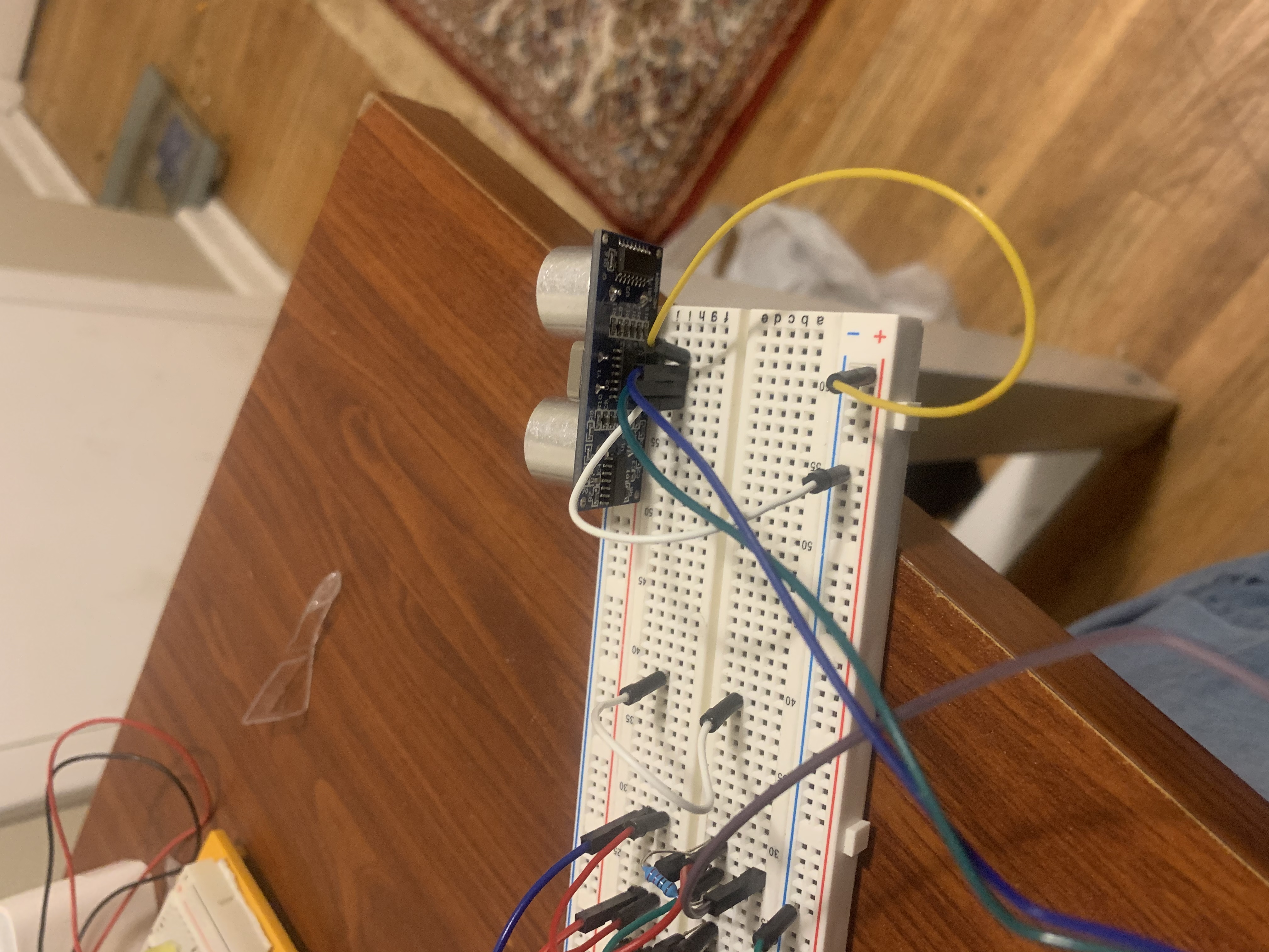
Ping Sensor
-
Arduino Board
-
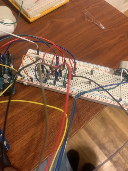
Circuitry

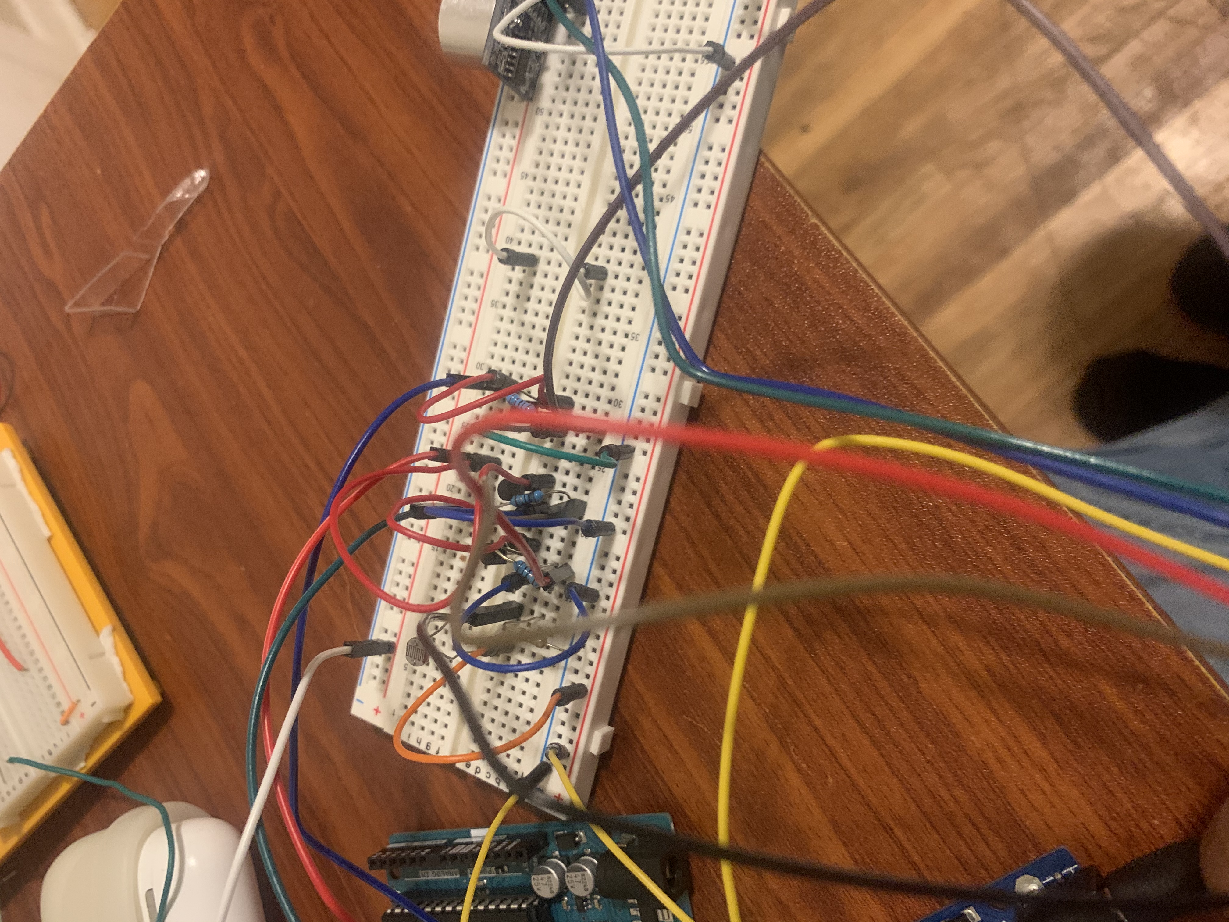
Group #19
Inspiration
We figured that next semester, we'd often be in our dorms. Thus, we thought we might as well spice up our dorms with some LED Lights! We thought it'd be neat to have a LED light strip turn on when it's dark, and to get notified if your door is open.
General Objective
For our project, we aim to turn on and off a LED strip with sunlight. If the photoresistor in the circuit senses significant amounts of light, then the LED strips will be off, and if the photoresistor senses little amount of light, then the LED strips will be on. Wifi will be integrated into the project through a clock, keeping track of how long the light was on for and displaying it on a dashboard. We also used Wifi to change the colors of the LED Strip via sliders. Furthermore, we'll incorporate a ping sensor to determine whether a door has been opened. And if a door has been opened, then a LED will turn on, signaling that the door is open. For the ping sensor, we used Wifi to keep track of the measurements of the ping sensor.
How we built it:
LED Light Strip: Our project incorporates a LED light strip that is connected to the breadboard. The Node MCU is programmed such that when the photoresistor measures a light level under 200, or above 800 (we'll get into this later), the LED strip would turn on.
Photo resistor: The photoresistor in our project is connected to the NodeMCU. Due to the photoresistor having a slight issue and reporting values above 800 when entirely covered, we programmed the NodeMCU to send power to the LED strips when the photo resistor read above 800 and below 200.
Ping Sensor: The ping sensor in our project is connected to the NodeMCU. The NodeMCU is programmed such that if the Ping sensor reads a distance greater than some distance (depends on where the door is relative to the breadboard), a LED will turn on.
9 Volt Battery: We used a 9V battery in our project to supply enough power to the LED strip.
Blynk App: Within the Blink app, there are five widgets. 3 of the widgets are sliders that are responsible for providing the RGB values of the LED light strip. One of the widgets is a graph that represents the return from the ping sensor. And the last widget is a stopwatch that shows how long the LED light strips have been on (in seconds).
Challenges
A significant challenge for us was to get our LED light strip to work as we came across issues with the photoresistor. Sometimes the photoresistor would output abnormally high values even when covered and other times, covering the photoresistor wouldn't affect the read outs. To deal with this, we smoothed out the photoresistor values and also set it that if the photoresistor read above 800, the LED light strip would turn on.
What we learned
Sometimes parts in the circuit can act faulty even though they aren't faulty. For example, the photoresistor acted faulty but we could adjust the code such that the photoresistor wasn't faulty. We also learned how to use a transistor in a circuit and how to use Blynk to function as a stopwatch.
Future advancements
Make the ping sensor more accurate. The ping sensor currently has difficulty when the surface behind the door isn't smooth. Thus, in the future, we'd aim to make the circuit more robust as in the real world, the surfaces behind doors isn't always smooth.
Distribution of Work:
Richard's work: Richard wired the ping sensor and the LED that turns on when the door is open. He implemented the code for using the ping sensor to turn on the LED. He also wrote the code for creating a stopwatch on the Blynk app. Another thing that Richard did was write up the the description of the project on devpost, with a summary of what the different components in the circuit did.
Abdinajib's work:
Abdi wired the LED strip to turn on when the photosensor detected lower amounts of light. Abdi implemented the code for the photosensor and the LED strips that worked with NodeMCU. Abdi figured out how to turn on/off the flow of the external power supplies. Abdi wrote the code change colors of the LEDs strips to use with the Blynk app.
Code snippet (operating stopwatch):
void stopwatchEvent() { static int value = 0; int raw = analogRead(sensorPin0); value = ((value * 15) + raw) / 16; if (value <= 200 || value >= 800) { // when the photoresistor is on. stopwatch = stopwatch + 1.0; // increments the time counter. } Blynk.virtualWrite(V6, stopwatch / 10); // updates the value every second. }


Log in or sign up for Devpost to join the conversation.