-
-
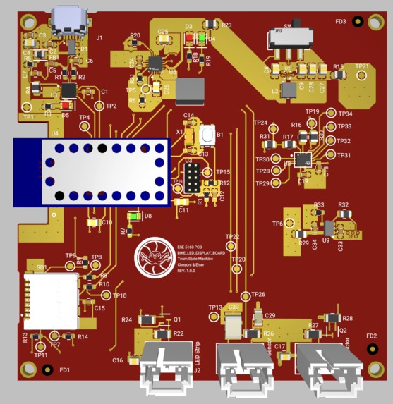
Altium PCB
-
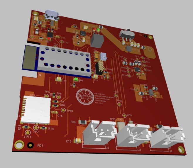
Altium PCB 3D
-
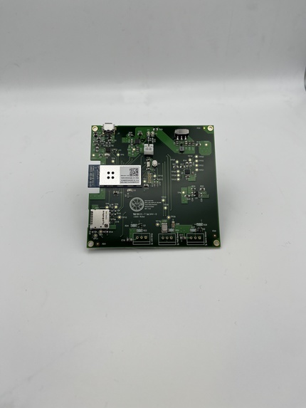
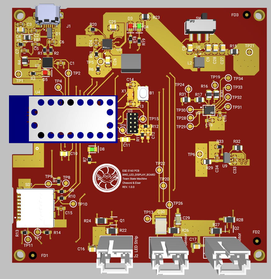
PCB
-
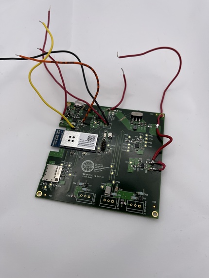
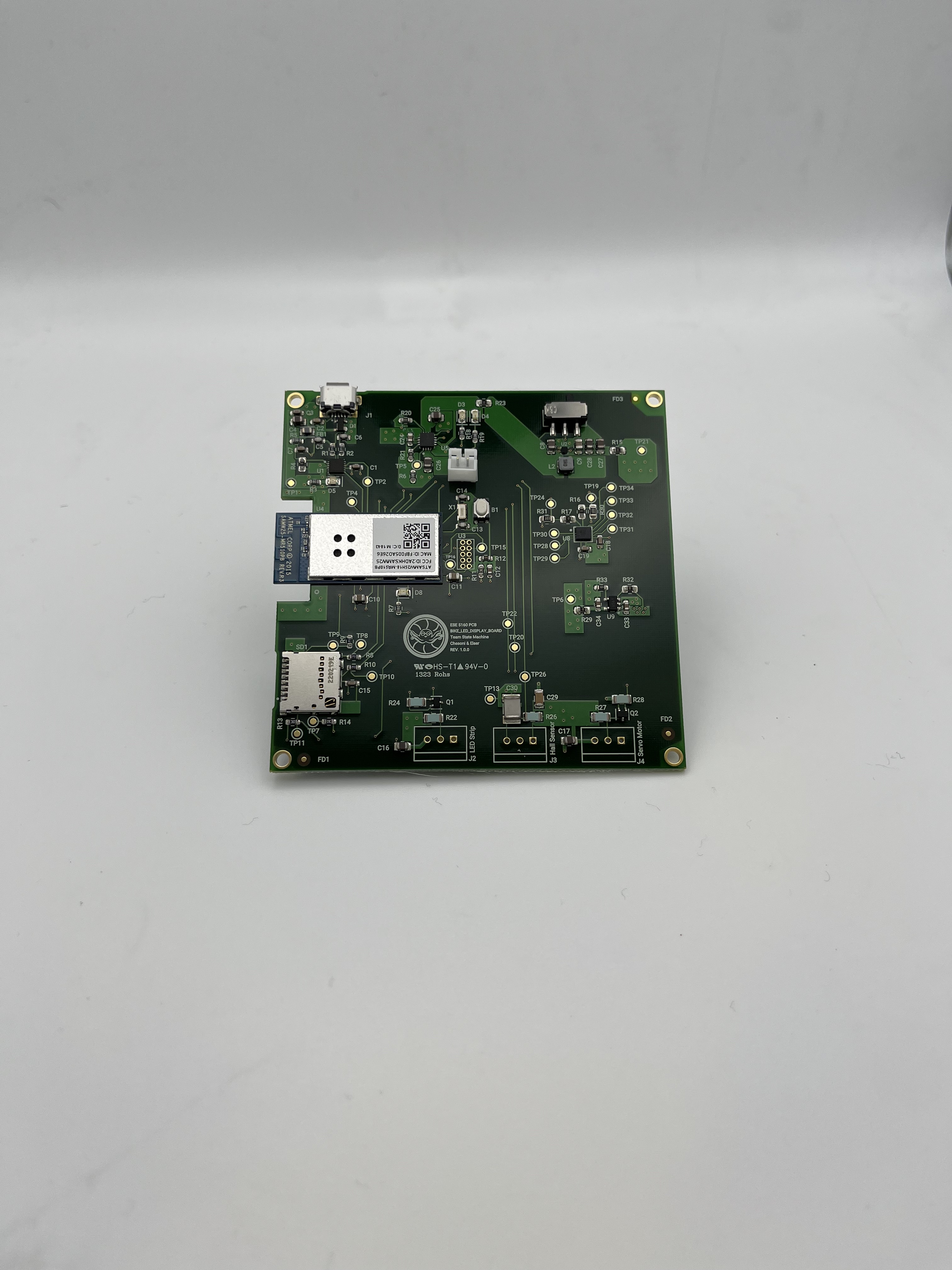
Modified PCB
-
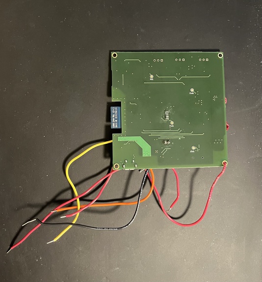
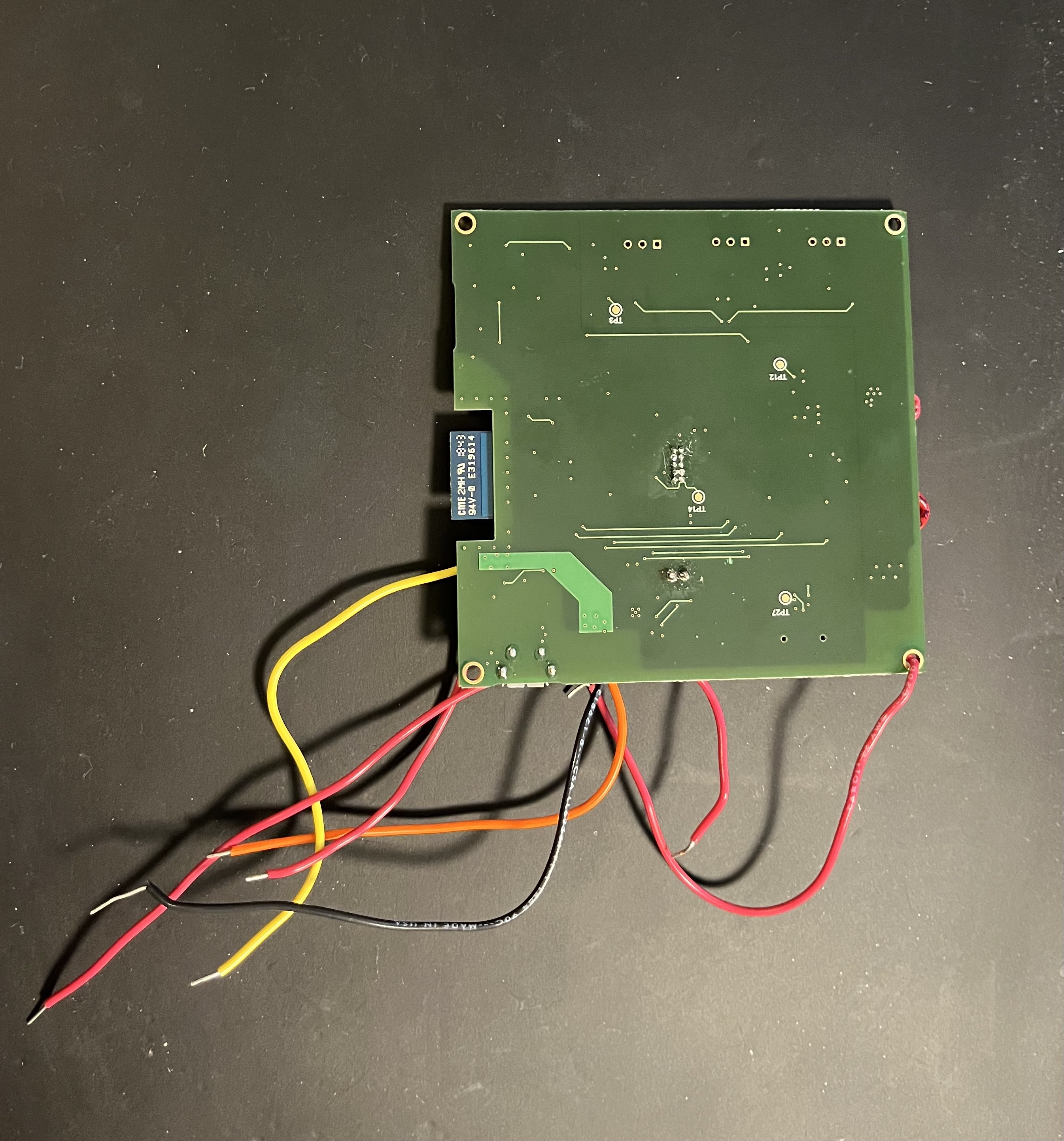
Modified PCB Bottom
-

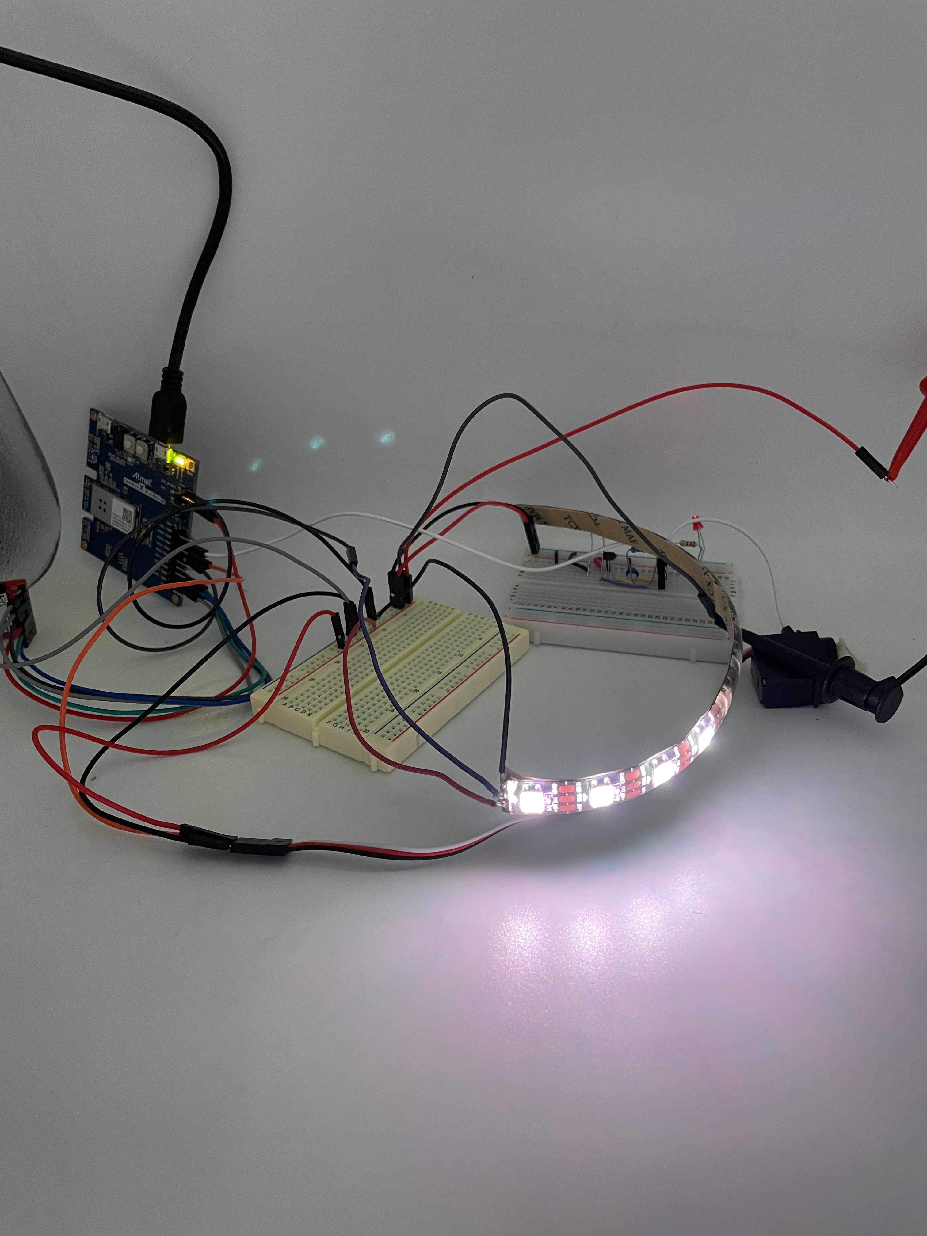
PCB with Components Attached
-
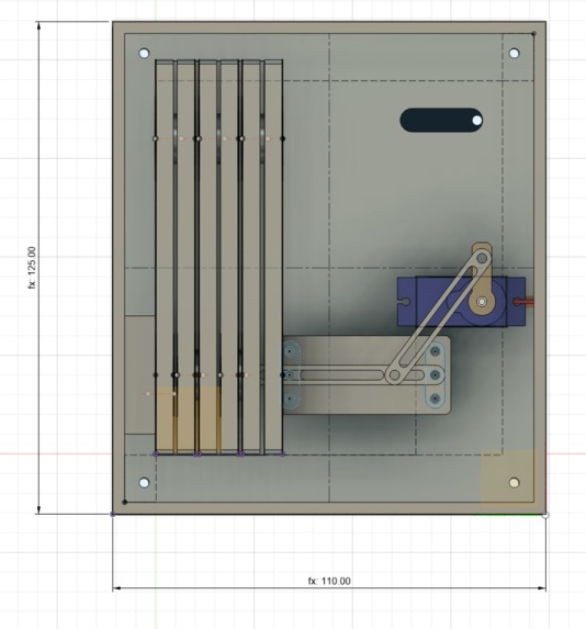
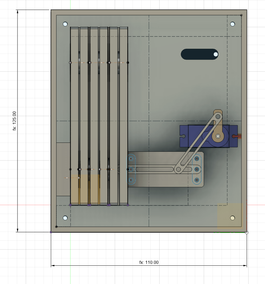
CAD Model
-
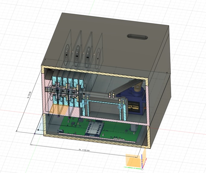
CAD Model Section Analysis
-
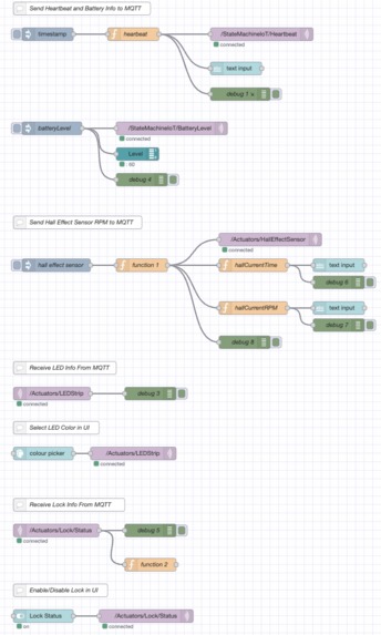
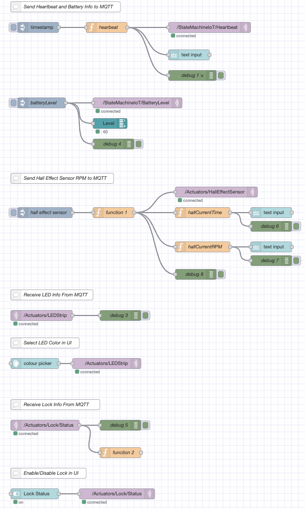
Node-Red Backend
-

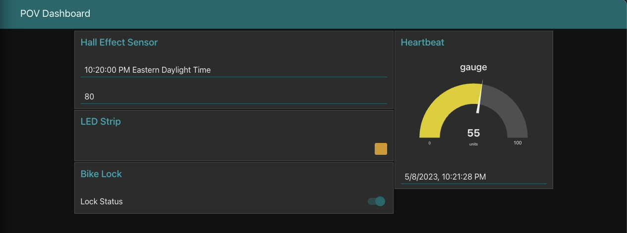
Node-Red Dashboard
-
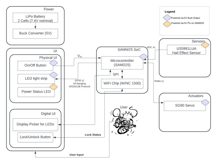
System Block Diagram


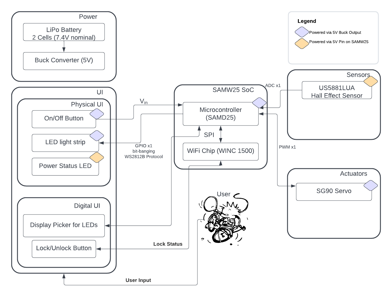
Inspiration
We both do a fair amount of biking and the two most important aspects of biking are being visible and looking cool. Thankfully, LEDs are bright and noticeable and nothing is cooler than the persistence-of-vision effects of spinning LEDs. Nothing.
What It Does
Our bike light is able to change patterns on an LED strip that can be attached along a wheel spoke in order to create cool effects while the wheel spins. It can calculate the rotations per minute using a hall effect sensor (and magnet attached to the frame) and update the LED pattern during each rotation, for even cooler effects. There is also a locking mechanism controlled by a servo, which prevents the wheel from spinning when in locked mode.
How We Built It
We designed a custom PCBA using Altium Designer, based around a SAMW25 MCU.
Challenges We Ran Into
WS2812B Protocol
The WS2812B protocol used by the LEDs is not natively supported by the SAMW25, nor was a useable library available, so we had to bit-bang it. Since this protocol runs at 800kHz, which is relatively fast for the 48mHz cpu on the SAMW25, we had to set up PWM using DMA, which was both tricky and memory intensive.
Node Red Troubles
We were not able to connect Node Read to our HiveMQ Web Client. We posted on Ed discussion and asked several other teams for help, but all concluded that the current setup should work. To this day we have no idea why it does not.
Memory Troubles:
Each bit communicated by the WS2812B protocol had to be represented by two bytes, persistent in memory, as part of the DMA. Since each LED requires 24 bits of signal, each LED was 48 bytes. This did not initially seem too large, but when combined with the download of a 31kb file for the over-the-air firmware update, we ran into mysterious hard-faults. Reducing the number of LEDs used stopped the hard-faults, so we believe this was a memory constraint issue.
USB Troubles:
We accidentally switched the RX and TX pins for serial communication via USB, and placed an incorrect value resistor here as well. This meant we had to use an off-board FTDI/USB cable and bypass this part of our board.
Power Troubles:
We used a small ball grid array (BGA) boost/passthrough as part of our power conversion. Unfortunately, all boards we received had shorts between pins of this minuscule component, meaning we had to bypass this part of our PCBA.
SD Card
The incorrect resistors mentioned as part of the USB troubles were also used here. What should have been 27 ohm resistors were 27k ohm resistors, meaning we could mount the SD card but could not correctly write to it. We damaged the PCBA while trying to fix this, and ultimately moved forward with dev boards only.
Accomplishments That We're Proud Of
This was our first custom PCBA, and our second time working with an MCU without using Arduino, both of which were fun challenges! Though things did not go as planned, we're extremely proud of the work we did to create our first PCBA, and strengthen skills, such as leveraging datasheets to layout ideal schematics. Getting the WS1218B protocol to work was also very gratifying.
What We Learned
Your first PCB will never be manufactured correctly; plan accordingly! Leave room for rework, and make it easy to do so.
What's Next for State Machine
- More intricate patterns utilizing the RPM data from the Hall Sensor
- Connecting the IoT dashboard to CLI
- Fabricating parts for the lock, and to mount the device to a bike wheel

Log in or sign up for Devpost to join the conversation.