-
-

Team project and team members.
-
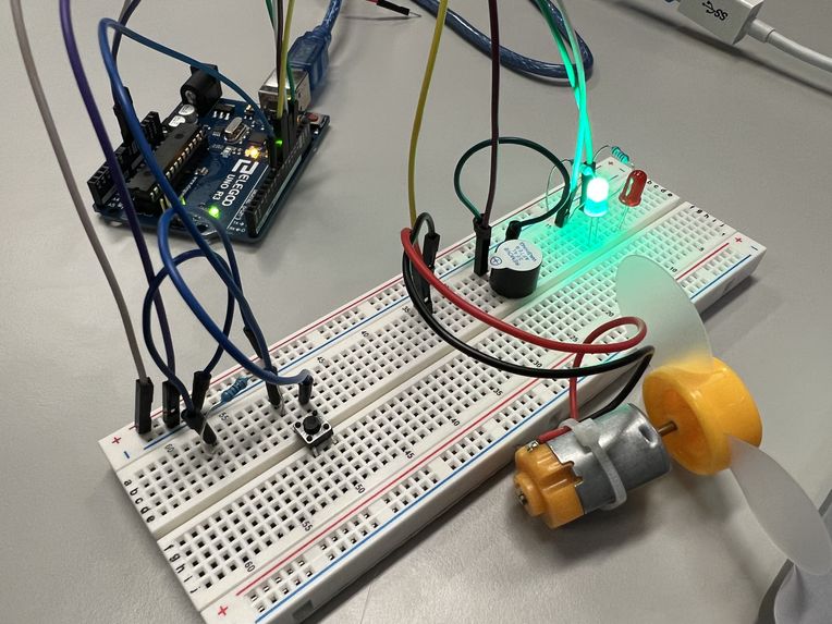
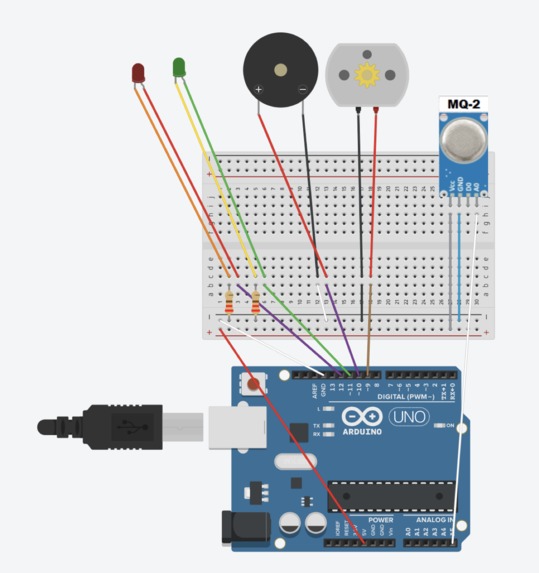
Initial implementation of the LEDs, buzzer and fan. At this stage we did not have the mq2 smoke detector so we used a button to imitate it.
-
Implementation of a bigger, more programmable buzzer, as well as making sure the circuit can be readily switched with the mq2 component.
-
Implementing a tune for the buzzer. One resembles a fire alarm, while the other represents an air raid.
-

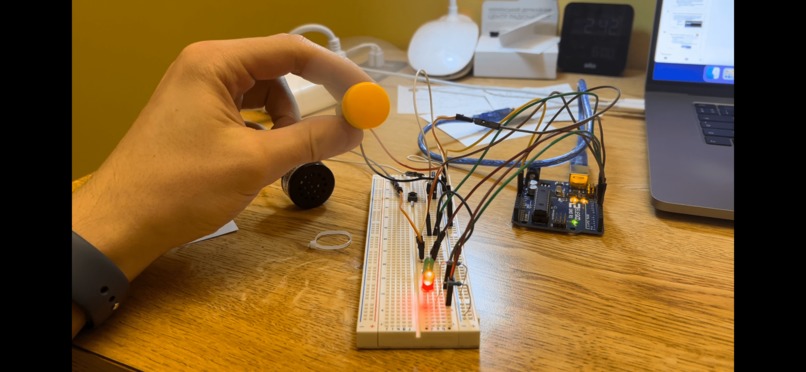
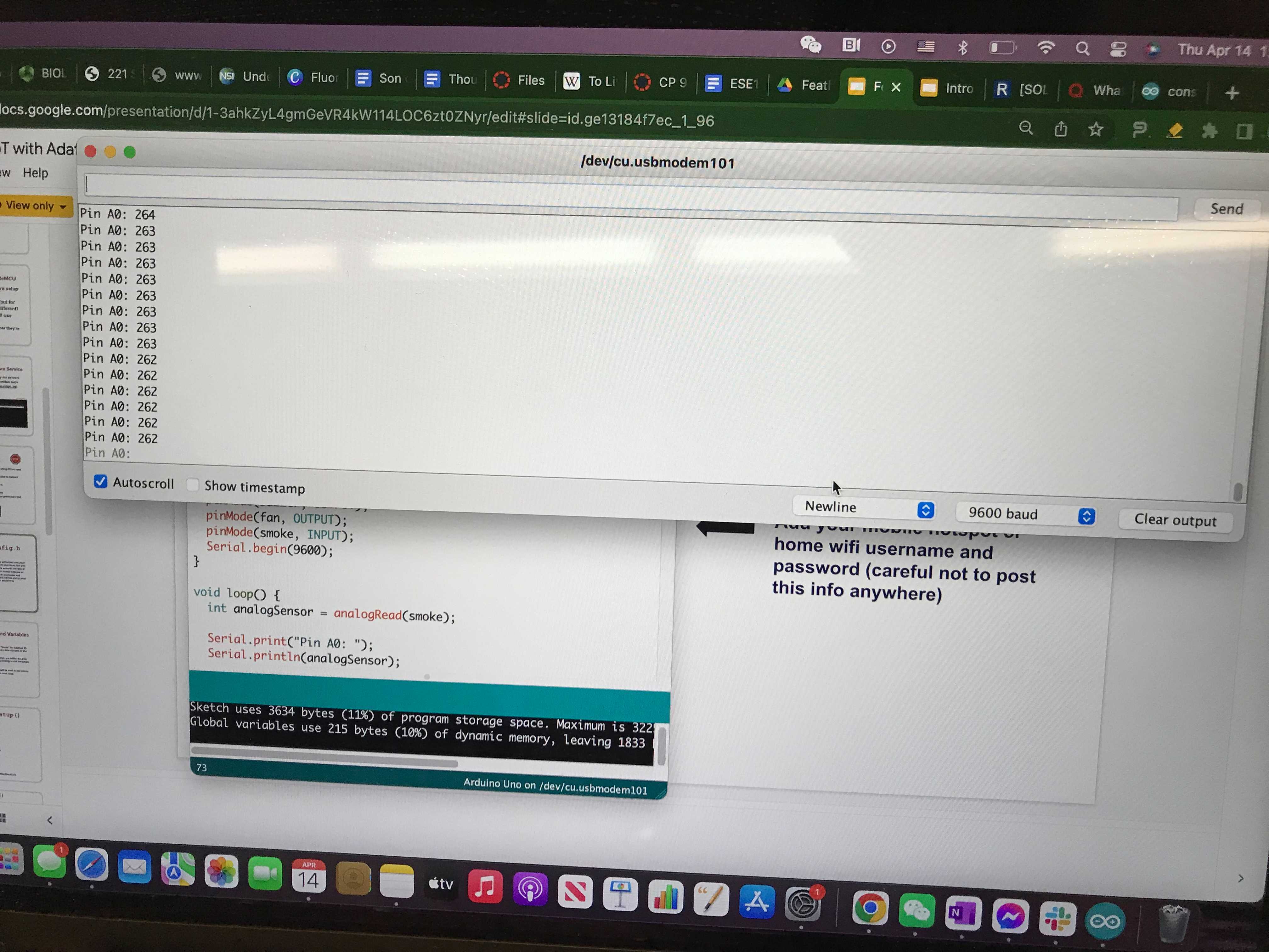
After the smoke detector arrived, we implemented it, and were able to get the readings from it into the serial monitor.
-
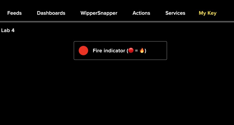
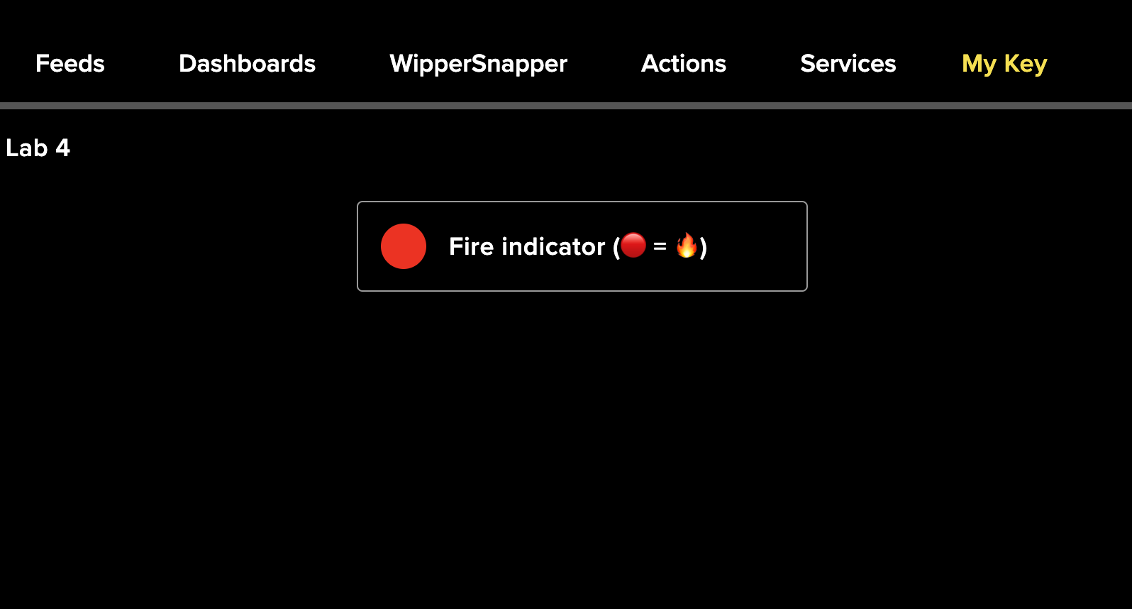
We implemented the Iot huzzah feather component to indicate when there was smoke present by changing the color on the Adafruit dashboard.
-

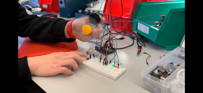
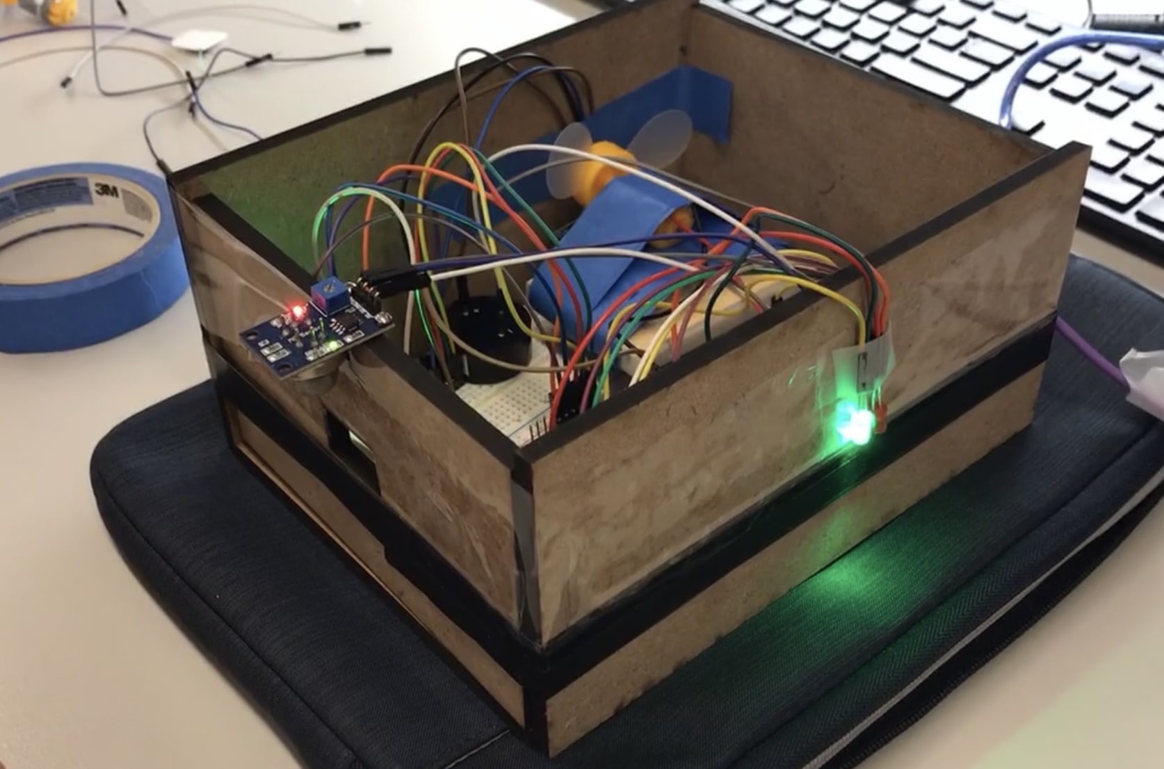
We built a box to keep everything together, and to make sure that components could work without having to hold them up ourselves.
-
Part 1
-

Part 2&3


Video
Google doc with additional information
Our Design Process, Iterations, and Challenges We Faced
First, we designed the sensor and its most immediate component first (fan, buzzer, and pins). Once we were certain that the impetus could be read by the MQ-2 sensor, we moved on to work on the IoT component. After many attempts at various possible inputs to the Huzzah Feather, we decided to use the motion of the fan as a direct input and coded the Feather component accordingly. The broader design of the smoke detector design had largely remained the same throughout the design process. However, we did previously have the fan as a component on the exterior to blow out the smoke if it’s nearby. In struggling to identify a reliable input to the Huzzah Feather, we ultimately chose to use its motion to indicate “smoke” or “no smoke”. We had quite some trouble determining what to use as input to the Huzzah Feather and can reliably parallel the presence and absence of smoke. Ultimately, we designed to use a fan component to block the distance sensor. Since a moving fan would render the sensor unable to detect a smaller distance, it would indicate the presence of fire.
Technology Description
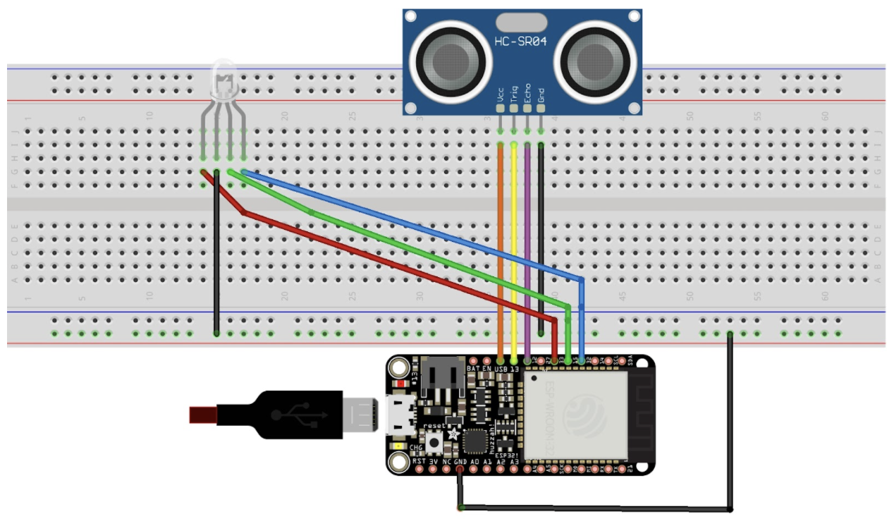
We used an MQ-2 smoke detector that’s sensitive to LPG, Smoke, Alcohol, Propane, Hydrogen, Methane, and Carbon Monoxide. To indicate the presence/absence, we use red and green LED pins, a 3-6 motor with a fan attached, and a buzzer. For the IoT component, we use a Huzzah ESP32 Feather with a ping sensor as input. The ping sensor at “no smoke” would be blocked by the fan, which is programmed to indicate no smoke on the Adafruit dashboard. When the MQ-2 sensor detects smoke, the fan will be turned to HIGH and its motion will render the ping sensor to detect a higher distance that’s programmed to indicate “smoke” on the Adafruit dashboard.
What We Learned
We learned how many mistakes can go into even simple steps, as we’ve had to troubleshoot the use of wrong libraries/ports to incorrect wirings physically. This reemphasized the notion that the inability of the product to function properly could be the result of mistakes in many components or in just one.
Next Steps
One possible next step is to use a more reliable and resettable input to the Huzzah Feather component rather than using a fan to block the distance sensor and using its “On” and “Off” to dictate the detection of fire. A more reliable method would be deploying a Servo component that has a more predictable range of motion.
Code Part 1:
//Initiating values
int redLed = 12;
int greenLed = 11;
int buzzer = 10;
int fan = 9;
int smoke = A5;
// Your threshold value
int minValue = 400;
void setup() {
  pinMode(redLed, OUTPUT);
  pinMode(greenLed, OUTPUT);
  pinMode(buzzer, OUTPUT);
  pinMode(fan, OUTPUT);
  pinMode(smoke, INPUT);
  Serial.begin(9600);
}
void loop() {
  int analogSensor = analogRead(smoke);
  Serial.print("Pin A0: ");
  Serial.println(analogSensor);
  // Checks if there is smoke
  if (analogSensor > minValue)
  {
    //Conditions for smoke present
    digitalWrite(redLed, HIGH);
    digitalWrite(greenLed, LOW);
    digitalWrite(fan, HIGH);
     for (int i = 0; i < 1; i++) {
    //The two tone sound
    for (int i = 0; i < 15; i++) {
      if (i % 2 == 0) {
        tone(buzzer, 600, 200);
      }
      else {
        tone(buzzer, 800, 200);
      }
        delay(200);
      }
    delay(500);
    //The air raid sound
    for (int l = 0; l < 2; l++) {
      int j = 200;
      while (j < 800) {
        tone(buzzer, j, 200);
        j = j + 10;
        delay(40);
      }
      delay(500);
     }
  }
  }
  else
  {
    //Conditions when smoke is absent
    digitalWrite(redLed, LOW);
    digitalWrite(greenLed, HIGH);
    digitalWrite(fan, LOW);
    noTone(buzzer);
  }
  delay(100);
}
Code Part 2
#include "config.h"
// set up the ‘colors’ and ‘distances’ feed
AdafruitIO_Feed *distances = io.feed("distance");
AdafruitIO_Feed *colors = io.feed("colors");
// these correspond to the pins on your Huzzah/Feather32 board
#define trigPin 13    //Pin13/A12 on Feather32
#define echoPin 12    //Pin12/A11 on Feather32
//Virtual Pins as channels for sending any data
const int greenPin = 27; //Pin27/A10 on Feather32
const int redPin = 33;   //Pin33/A9 on Feather32
const int bluePin = 15;  //Pin15/A8 on Feather32
// now, we will send this value to the cloud to tell it which color we want to show
// blue = 0, green = 1, and red = 2
int color;
void setup() {
  // declare pins as inputs and outputs
  pinMode (trigPin, OUTPUT );
  pinMode (echoPin, INPUT );
  pinMode (redPin, OUTPUT);
  pinMode (greenPin, OUTPUT);
  pinMode (bluePin, OUTPUT);
  // start the serial connection
  Serial.begin(115200);
  // wait for serial monitor to open
  while(! Serial);
  Serial.print("Connecting to Adafruit IO");
  // connect to io.adafruit.com
  io.connect();
  // wait for a connection
  while(io.status() < AIO_CONNECTED) {
    Serial.print(".");
    delay(500);
  }
  // we are connected
  Serial.println();
  Serial.println(io.statusText());
}
void loop() {
  // io.run(); is required for all sketches.
  // it should always be present at the top of your loop
  // function. it keeps the client connected to
  // io.adafruit.com, and processes any incoming data.
  io.run();
  long duration , distance;
  digitalWrite (trigPin , LOW ); // start trig at 0
  delayMicroseconds (2);
  digitalWrite (trigPin , HIGH ); // the rising edge of trig pulse
  delayMicroseconds (10); // decides duration of trig pulse
  digitalWrite (trigPin , LOW ); // falling edge of the trig pulse
  // NOTE: echo pin reads HIGH till it receives the reflected signal
  duration = pulseIn (echoPin , HIGH ); // reading the duration for which echoPin was HIGH gives
  // the time the sensor receives a reflected signal at the echo pin
  distance = (duration / 2) / 29.1; // calculate the distance of the reflecting surface in cm
  // this section lights up LED based on distance
  // case 1: LED is red
  if (distance<12 && distance>=0){
    color = 2;
    digitalWrite(redPin, HIGH);
    digitalWrite(greenPin, LOW);
    digitalWrite(bluePin, LOW);
  }
  // case 2: LED is green
  if (distance<40 && distance>=12){
    color = 1;
    digitalWrite(redPin, LOW);
    digitalWrite(greenPin, HIGH);
    digitalWrite(bluePin, LOW);
  }
  // case 3: LED is blue
  if (distance>=40){
    color = 0;
    digitalWrite(redPin, LOW);
    digitalWrite(greenPin, LOW);
    digitalWrite(bluePin, HIGH);
    Serial.println("Out of Range"); // print when distance is not in either range
  }
  Serial.println("Distance is:    ");
  Serial.println(distance);
  colors->save(color);
  delay(2000);
  distances->save(distance);
  // Adafruit IO is rate limited for publishing, so a delay is required in
  // between feed->save events. In this example, we will wait three seconds
  // (1000 milliseconds == 1 second) during each loop.
  delay(2000);
}
Code Part 3
Due to privacy reasons I removed any personal information and keys from this section. In addition to that, all the hashtags have been removed as they mess up the code indentation on devpost. Please refer to the google drive for true code
include "AdafruitIO_WiFi.h"
// comment out the following lines if you are using fona or ethernet
define WIFI_SSID "HP Setup" //or hotspot name
define WIFI_PASS "detkin101"
if defined(USE_AIRLIFT) || defined(ADAFRUIT_METRO_M4_AIRLIFT_LITE) ||         \
    defined(ADAFRUIT_PYPORTAL)
// Configure the pins used for the ESP32 connection
if !defined(SPIWIFI_SS) // if the wifi definition isnt in the board variant
// Don't change the names of these #define's! they match the variant ones
define SPIWIFI SPI
define SPIWIFI_SS 10 // Chip select pin
define NINA_ACK 9    // a.k.a BUSY or READY pin
define NINA_RESETN 6 // Reset pin
define NINA_GPIO0 -1 // Not connected
endif
AdafruitIO_WiFi io(IO_USERNAME, IO_KEY, WIFI_SSID, WIFI_PASS, SPIWIFI_SS,
                   NINA_ACK, NINA_RESETN, NINA_GPIO0, &SPIWIFI);
else
AdafruitIO_WiFi io(IO_USERNAME, IO_KEY, WIFI_SSID, WIFI_PASS);
endif
/******************************* FONA **************************************/
// the AdafruitIO_FONA client will work with the following boards:
//   - Feather 32u4 FONA -> https://www.adafruit.com/product/3027

// uncomment the following two lines for 32u4 FONA,
// and comment out the AdafruitIO_WiFi client in the WIFI section
// include "AdafruitIO_FONA.h"
// AdafruitIO_FONA io(IO_USERNAME, IO_KEY);
/**************************** ETHERNET ************************************/
// the AdafruitIO_Ethernet client will work with the following boards:
//   - Ethernet FeatherWing -> https://www.adafruit.com/products/3201
// uncomment the following two lines for ethernet,
// and comment out the AdafruitIO_WiFi client in the WIFI section
// #include "AdafruitIO_Ethernet.h"
// AdafruitIO_Ethernet io(IO_USERNAME, IO_KEY);

Log in or sign up for Devpost to join the conversation.