-
-
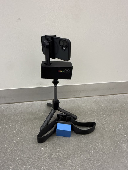
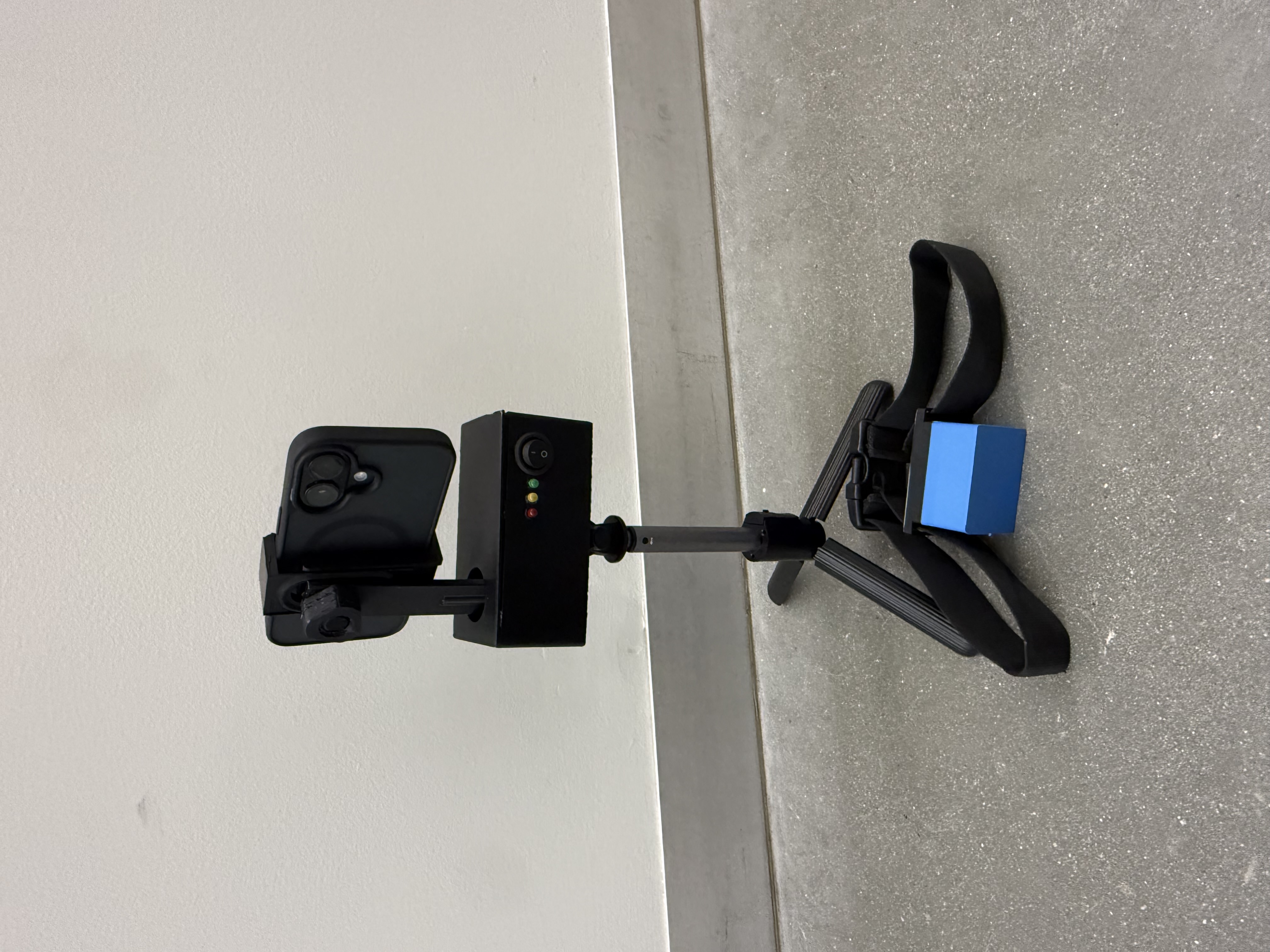
Final Product
-
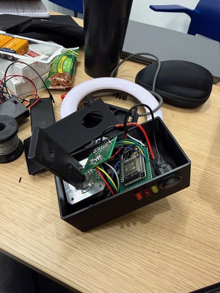
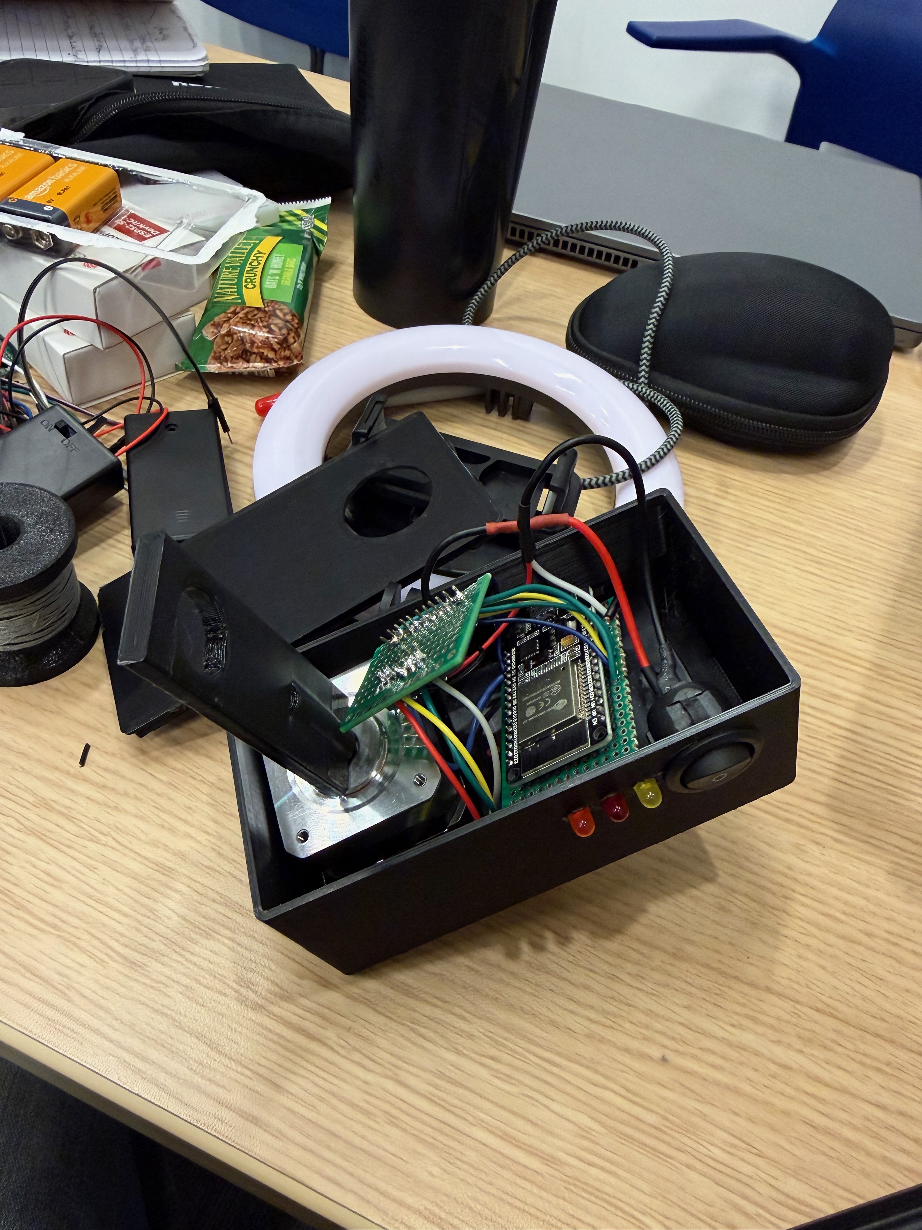
Tripod Hardware
-

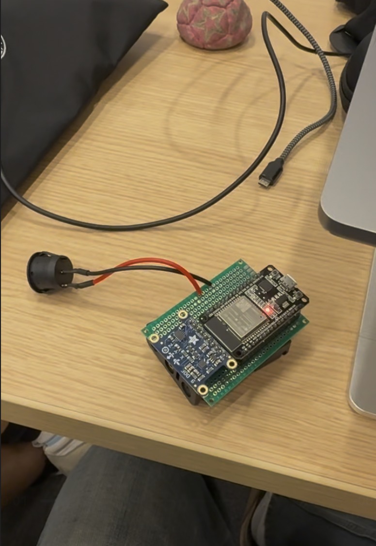
Airtag Hardware
-

Lucas's younger brother, Jacob

You can see our presentation here.
Inspiration
Lucas always films his younger brother at his soccer games. He often loses track of his brother among the crowded field, with 10 other players wearing the same kit. A computer vision or optical solution would struggle to pick his brother out of the other players on his team for the same reason Lucas struggles to see his brother, so we created hardware to a specific player on a soccer field.
What it does
The smart tripod uses positional data to keep a wireless transmitter in the center of a video frame. This transmitter polls and broadcasts data from a 9-axis IMU at ~100 Hz. The tripod calculates the relative location of the IMU and calculates the change in angle needed to make the stepper motor point directly at the device, all in real-time using a PID controller.
How we built it
Tripod: We customized a tripod we bought from target by adding a tracking attachment on the top. With custom 3D-printed hardware to attach to the base, house electronics, and hold a phone, this attachment rotates the cell phone holder using a Nema 17 stepper motor controlled by an ESP32 and Adafruit TB6612 motor driver.
Airtag: An ESP32 polls an 9-axis IMU (Adafruit LSM303DLHC and L3GD20) and UDP broadcasts via WiFi to the tripod ESP32. It is attached to the target player using a custom 3D-printed housing and clip on strap.
Challenges we ran into
SENSOR FUSION / PID: Using the accelerometer + gyroscope + magnetometer sensor combination does not provide a super precise way of getting relative location. The double integration to go from acceleration to location squares the error term.
SIGNAL HANDLING / FILTERING: We initially used a hardware low-pass filter to prevent noise from the high-voltage stepper motor, however this was not working as expected and we had trouble debugging, so we scrapped it. We also tried several filters (e.g. Kalman filtering) to reduce noise on the IMU data.
CIRCUIT DEBUGGING: The buck converter circuit for the 18V->5V was supplying zero power. We cut the circuit off of the perfboard after frustrated debugging. Shortly after, we realized the Vin battery connection was unfortunately not soldered (meaning the circuit may have worked fine).
FAILED 3D PRINTS: The error margin on the printers was inconsistent between colors and print to print. To counter this we decreased our margin of error and manually filed prints down to precise size. Additionally, 3D prints left to print overnight failed. To trouble shoot we had to shave material from the print to decrease the reprint time.
Accomplishments that we're proud of
TEAMWORK: We have never worked together in a team, yet from the minute we got together jokes were flying and ideas where flowing. When it came time to get progress on our project we were able to get technical on the flip of a switch
PRODUCT: We were super happy with how this turned out from a hardware perspective. Lots of detailed soldering was done to fit the devices into such a small frame, and our 3D prints look amazing and work great. We were super stoked at how the electronics specifically attached to our tripod base.
What we learned
Despite being a rushed and high-velocity hackathon, we learned that upfront design is key. Don't rush to conclusions or into actions. Methodically move through trouble shooting and looking through the entire design before acting.
What's next for Smart Tripod
We want to downsize the transmitter so that it will fit into a player's pocket (as the original intent of the device was). We would also like to add a GPS module to the transmitter so that it will give (low-rate) more accurate positional data that can be cross-referenced with the IMU.
Built With
- 3d-printers
- adafruit-breakout-boards
- esp32
- platformio
- vscode

Log in or sign up for Devpost to join the conversation.