-
-

Smart Shoe module attached as it would be in use
-

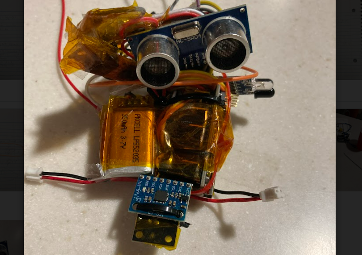
Module detail, showing the ultrasound and infared proximity sensors, as well as the IMU (front), and rechargeable batteries (left)

Inspiration
Retinal degeneration affects 1 in 3000 people, slowly robbing them of vision over the course of their mid-life. The need to adjust to life without vision, often after decades of relying on it for daily life, presents a unique challenge to individuals facing genetic disease or ocular injury, one which our teammate saw firsthand in his family, and inspired our group to work on a modular, affordable solution. Current technologies which provide similar proximity awareness often cost many thousands of dollars, and require a niche replacement in the user's environment; (shoes with active proximity sensing similar to our system often cost $3-4k for a single pair of shoes). Instead, our group has worked to create a versatile module which can be attached to any shoe, walker, or wheelchair, to provide situational awareness to the thousands of people adjusting to their loss of vision.
What it does (Higher quality demo on google drive link!: https://drive.google.com/file/d/1o2mxJXDgxnnhsT8eL4pCnbk_yFVVWiNM/view?usp=share_link )
The module is constantly pinging its surroundings through a combination of IR and ultrasonic sensors. These are readily visible on the prototype, with the ultrasound device looking forward, and the IR sensor looking to the outward flank. These readings are referenced, alongside measurements from an Inertial Measurement Unit (IMU), to tell when the user is nearing an obstacle. The combination of sensors allows detection of a wide gamut of materials, including those of room walls, furniture, and people. The device is powered by a 7.4v LiPo cell, which displays a charging port on the front of the module. The device has a three hour battery life, but with more compact PCB-based electronics, it could easily be doubled. While the primary use case is envisioned to be clipped onto the top surface of a shoe, the device, roughly the size of a wallet, can be attached to a wide range of mobility devices.
The internal logic uses IMU data to determine when the shoe is on the bottom of a step 'cycle', and touching the ground. The Arduino Nano MCU polls the IMU's gyroscope to check that the shoe's angular speed is close to zero, and that the module is not accelerating significantly. After the MCU has established that the shoe is on the ground, it will then compare ultrasonic and IR proximity sensor readings to see if an obstacle is within a configurable range (in our case, 75cm front, 10cm side).
If the shoe detects an obstacle, it will activate a pager motor which vibrates the wearer's shoe (or other device). The pager motor will continue vibrating until the wearer takes a step which encounters no obstacles, thus acting as a toggle flip-flop.
An RGB LED is added for our debugging of the prototype: RED - Shoe is moving - In the middle of a step GREEN - Shoe is at bottom of step and sees an obstacle BLUE - Shoe is at bottom of step and sees no obstacles
While our group's concept is to package these electronics into a sleek, clip-on plastic case, for now the electronics have simply been folded into a wearable form factor for demonstration.
How we built it
Our group used an Arduino Nano, batteries, voltage regulators, and proximity sensors from the venue, and supplied our own IMU, kapton tape, and zip ties. (yay zip ties!)
I2C code for basic communication and calibration was taken from a user's guide of the IMU sensor. Code used for logic, sensor polling, and all other functions of the shoe was custom. All electronics were custom.
Testing was done on the circuits by first assembling the Arduino Microcontroller Unit (MCU) and sensors on a breadboard, powered by laptop. We used this setup to test our code and fine tune our sensors, so that the module would behave how we wanted. We tested and wrote the code for the ultrasonic sensor, the IR sensor, and the gyro separately, before integrating as a system.
Next, we assembled a second breadboard with LiPo cells and a 5v regulator. The two 3.7v cells are wired in series to produce a single 7.4v 2S battery, which is then regulated back down to 5v by an LM7805 regulator chip. One by one, we switched all the MCU/sensor components off of laptop power, and onto our power supply unit. Unfortunately, this took a few tries, and resulted in a lot of debugging.
. After a circuit was finalized, we moved all of the breadboard circuitry to harnessing only, then folded the harnessing and PCB components into a wearable shape for the user.
Challenges we ran into
The largest challenge we ran into was designing the power supply circuitry, as the combined load of the sensor DAQ package exceeds amp limits on the MCU. This took a few tries (and smoked components) to get right. The rest of the build went fairly smoothly, with the other main pain points being the calibration and stabilization of the IMU readings (this simply necessitated more trials) and the complex folding of the harnessing, which took many hours to arrange into its final shape.
Accomplishments that we're proud of
We're proud to find a good solution to balance the sensibility of the sensors. We're also proud of integrating all the parts together, supplying them with appropriate power, and assembling the final product as small as possible all in one day.
What we learned
Power was the largest challenge, both in terms of the electrical engineering, and the product design- ensuring that enough power can be supplied for long enough, while not compromising on the wearability of the product, as it is designed to be a versatile solution for many different shoes. Currently the design has a 3 hour battery life, and is easily rechargeable through a pair of front ports. The challenges with the power system really taught us firsthand how picking the right power source for a product can determine its usability. We were also forced to consider hard questions about our product, such as if there was really a need for such a solution, and what kind of form factor would be needed for a real impact to be made. Likely the biggest thing we learned from our hackathon project was the importance of the end user, and of the impact that engineering decisions have on the daily life of people who use your solution. For example, one of our primary goals was making our solution modular and affordable. Solutions in this space already exist, but their high price and uni-functional design mean that they are unable to have the impact they could. Our modular design hopes to allow for greater flexibility, acting as a more general tool for situational awareness.
What's next for Smart Shoe Module
Our original idea was to use a combination of miniaturized LiDAR and ultrasound, so our next steps would likely involve the integration of these higher quality sensors, as well as a switch to custom PCBs, allowing for a much more compact sensing package, which could better fit into the sleek, usable clip on design our group envisions.
Additional features might include the use of different vibration modes to signal directional obstacles and paths, and indeed expanding our group's concept of modular assistive devices to other solution types.
We would also look forward to making a more professional demo video Current example clip of the prototype module taking measurements:(https://youtube.com/shorts/ECUF5daD5pU?feature=share)
Built With
- arduino
- imu
- irsensor
- mpu
- soldering
- ultrasound


Log in or sign up for Devpost to join the conversation.