-
-
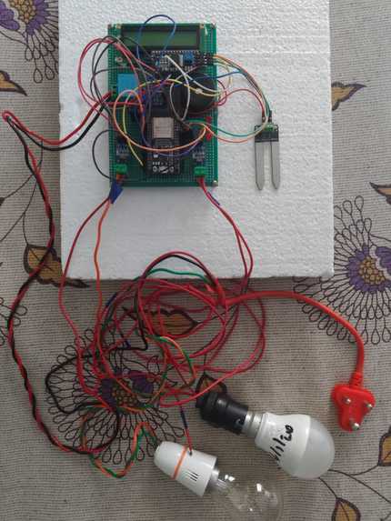
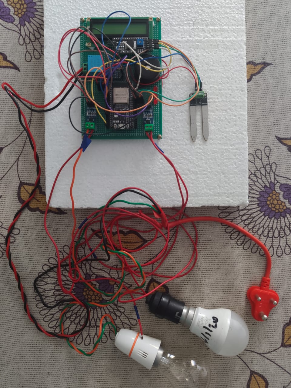
Hardware prototype setup featuring the ESP32 microcontroller interfaced with other hardware components.
-
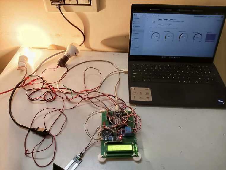
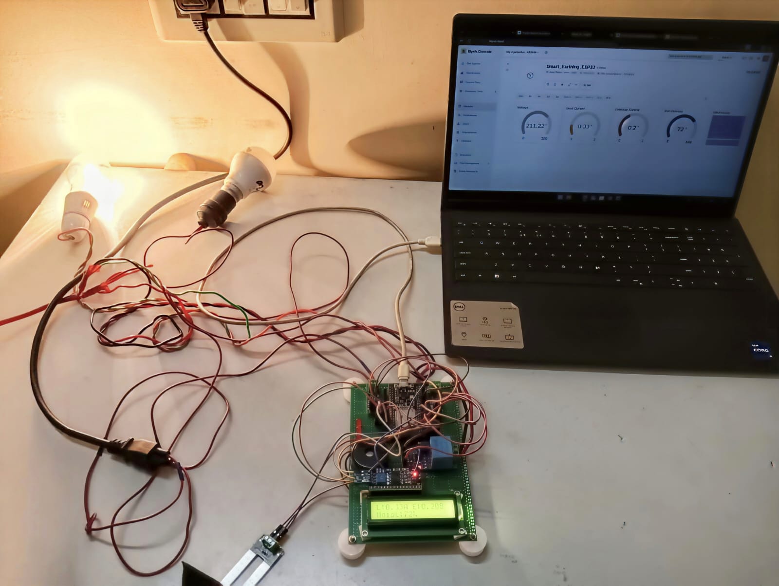
Complete physical test bench simulating public pole light electrical loads using dual lamps to monitor active baseline vs leakage current.
-
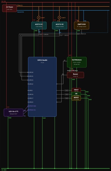
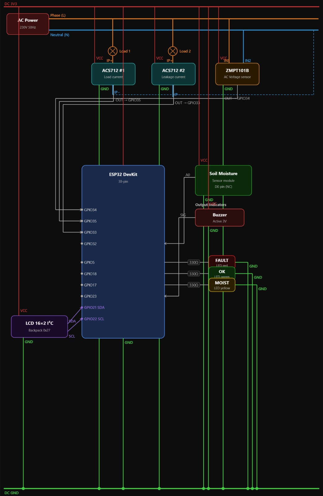
Detailed hardware schematic and pinout architecture mapping sensor connections and signal flows to the central ESP32 node.
-

Circuit wiring legend illustrating phase, neutral, earth paths, and signaling codes utilized across the earthing monitoring grid.
-
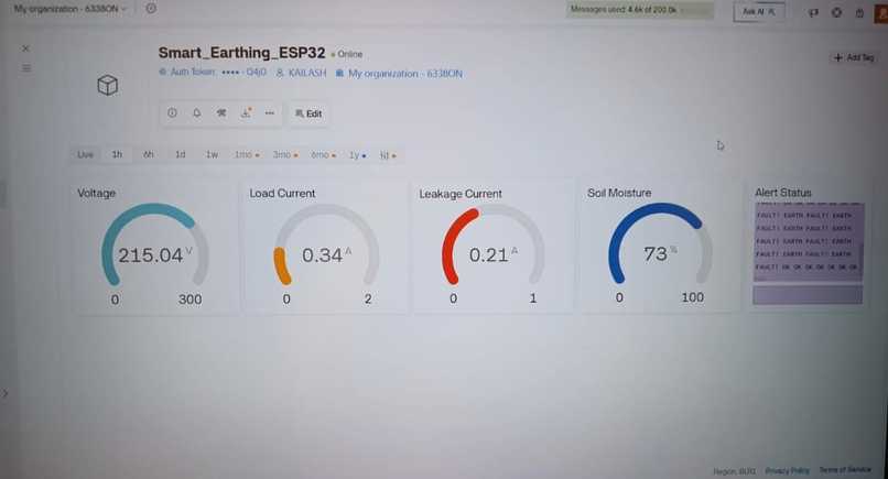
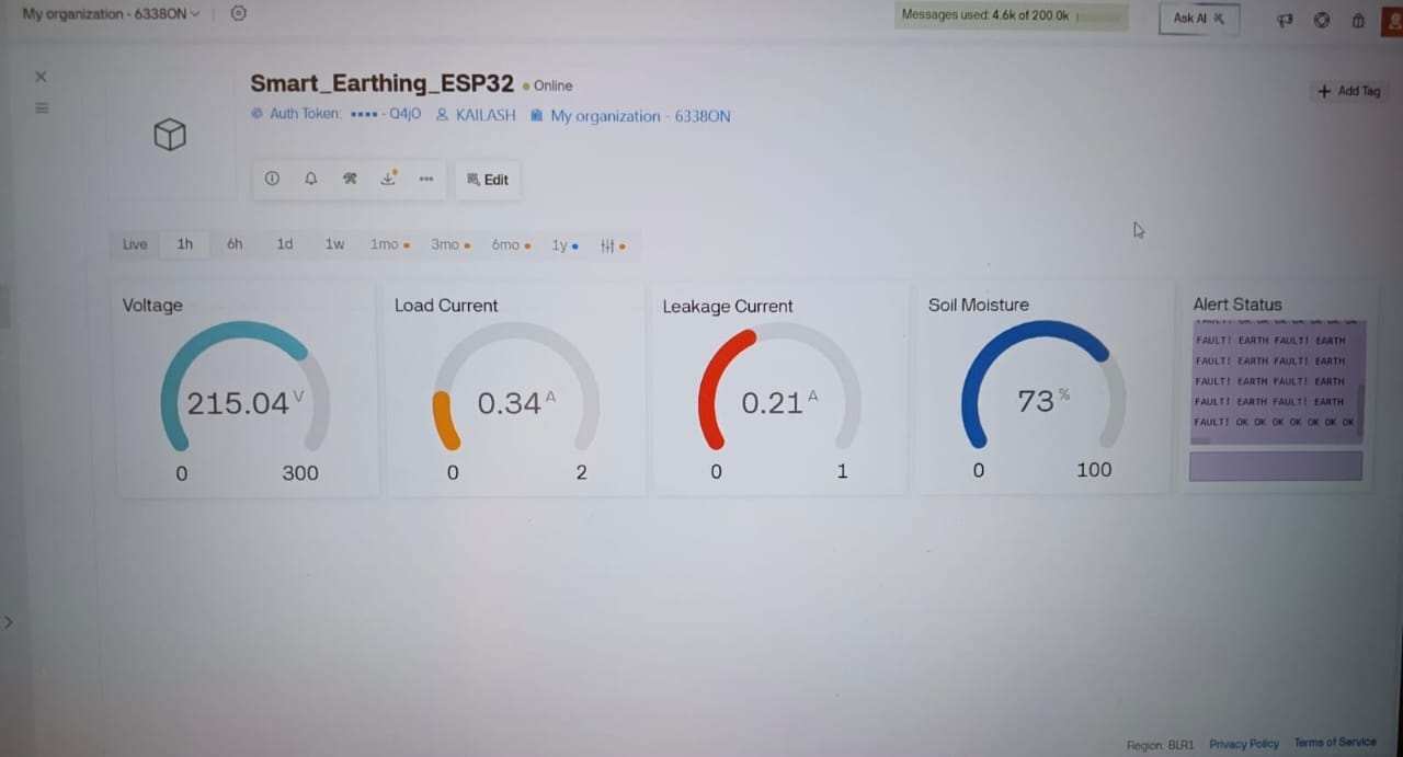
Real-time centralized Blynk IoT dashboard tracking live Vrms voltage, load currents, earth leakage spikes, and pit moisture levels.

## Inspiration
Public safety in modern urban infrastructure often relies on systems that remain invisible until they fail. In bustling parking areas and public transit station zones managed under the Smart Cities Mission, thousands of electrical pole lights illuminate our spaces daily. While these installations are theoretically equipped with automatic earth leakage protection switchgear, reality presents a severe operational vulnerability: hardware malfunctions, harsh weather corrosion, or system degradation can cause these protective safety layers to fail silently.
When earthing paths break or malfunction, an ordinary current leak transforms a public metal light pole into an active, lethal shock hazard for unsuspecting citizens. Under current infrastructure models, continuously auditing the grounding health and resistance values of thousands of distributed earth pits requires a massive, unsustainable scale of manual labor and manpower. I was inspired to solve this critical urban challenge independently by engineering an automated, sensor-based monitoring matrix that guarantees continuous safety tracking, eliminates manual inspections, and instantly alerts maintenance teams before a hazard can harm the public.
## What it does
The Smart Earthing Monitoring System is a fully functional, solo-developed IoT hardware system that continuously evaluates localized grounding health. It acts on three vital parameters to ensure public infrastructure remains safe:
- Load vs. Leakage Current Correlation: Continuously parses standard operating current against rogue current escaping through the chassis or safety earth lines.
- Dynamic Voltage Tracking: Monitors the Root Mean Square (RMS) voltage lines to identify potential spikes or drops linked to bad grounding paths.
- Soil Moisture/Resistivity Supervision: Tracks moisture content at the earth pit site, which is inversely proportional to the pit's contact resistance with the mass of earth.
If the system detects a leak exceeding a safety limit (configured at $0.30\text{ A}$), or if soil conditions degrade dangerously, it bypasses slow manual reporting. It instantly flags the event on a remote central cloud dashboard while simultaneously triggering hardware-level audible and visual indicators locally for field engineers.
## How we built it
I designed the entire system from scratch, compiling a custom physical sensing node anchored to an agile IoT telemetry cloud backend.
1. Hardware Subsystems
The system uses an ESP32 Microcontroller as its primary computation engine, taking advantage of its 12-bit ADC and processing speed. I integrated the following hardware:
- Dual ACS712 Current Sensors: Dedicated sensors isolated to discrete lines; one captures aggregate load current while the second monitors stray leakage current paths.
- ZMPT101B Voltage Sensor Transformer: Safely steps down high AC mains voltages into measurable analog wave profiles to track $V_{rms}$.
- Soil Moisture Probe: Embedded directly into the soil pit to monitor grounding conditions.
- Outputs & Local HMI: An I2C 16x2 LCD display handles real-time visual telemetrics. A dedicated alarm block features a 5V buzzer and 3 distinct status LEDs (OK, Earth Fault, Low Moisture) protected via 330$\Omega$ current-limiting resistors. Two standard bulbs act as the active electrical load simulation.
2. Firmware Mathematics Engine
The ESP32 firmware samples the analog sensors at high frequencies ($200\ \mu\text{s}$ periods) to compute true Root Mean Square (RMS) values rather than mere peak values, accounting for any distortion on the AC power line.
The algorithm tracks mains AC voltage via: \( V_{rms} = \sqrt{\frac{1}{N} \sum_{i=1}^{N} (V_{analog_i} - V_{offset})^2} \times \text{Calibration Factor} \)
Current monitoring utilizes a dual-stage computational architecture. The system maps the sampled analog voltages against raw calibrated hardware offsets ($loadOffset$ and $leakOffset$) obtained during an automated zero-load initialization phase: $$ I_{rms} = \sqrt{\frac{1}{N} \sum_{i=1}^{N} \left( \frac{V_{analog_i} - V_{offset}}{\text{Sensitivity}} \times \text{Calibration Factor} \right)^2} $$
Soil moisture calculation uses hardware mapping to convert raw high-impedance values into an active percentage representation: \( \text{Moisture \%} = \text{Map}\Big(\text{ADC}_{raw},\ \text{DryThreshold},\ \text{WetThreshold},\ 100,\ 0\Big) \)
3. IoT Cloud Architecture & Telemetry
Data packets are securely pushed over Wi-Fi using the Blynk IoT framework. I mapped out a centralized monitoring dashboard tied directly to the virtual register space:
- V0: Main AC Voltage ($V_{rms}$)
- V1: Active Load Current ($I_{rms}$)
- V2: Measured Leakage Current ($I_{rms}$)
- V3: Soil Moisture Percentage ($\%$)
- V4: Central System Status String Alert (
OK,EARTH FAULT!, orLOW MOISTURE)
## Challenges we ran into
- False-Positive Fault Debouncing: AC current sensors are susceptible to high-frequency transients and switching noise from inductive loads, which caused temporary math spikes that look like earth faults. I resolved this by coding a non-blocking software time-debounce mechanism. The firmware must read a continuous fault threshold violation for at least 3,000 milliseconds consecutively before committing to a true
EARTH FAULTclassification and tripping the buzzer. - Sensor Cross-Talk Interference: When zero load current was present, the current lines occasionally suffered from trace noise. I implemented an algorithm-level hard clamp in C++ that forces $LeakIrms` to instantly zero out if the load current drops below $0.05\text{ A}$, stabilizing the reporting data.
## Accomplishments that we're proud of
I successfully developed a fully automated end-to-end hardware prototype that operates entirely without manual oversight. I am incredibly proud of building a dependable sensor stabilization system in code that completely eliminates raw signal fluctuations, meaning municipal teams only receive genuine, actionable hazard alerts. Accomplishing this solo—spanning circuit design, sensor processing math, microcontroller firmware programming, and cloud visualization mapping—stands as a massive technical personal achievement.
## What we learned
Building this project as a solo engineer taught me how to move away from purely theoretical textbook electrical engineering formulas and step into real-world firmware implementation. I mastered complex analog signal processing, ADC attenuation adjustments on the ESP32, and learned how to build robust, noise-resilient digital smoothing routines. Most importantly, it showed me how IoT telemetry can modernize public safety utility management within our Smart Cities.
## What's next for Smart Earthing Monitoring System
The next step is moving from a localized Wi-Fi mesh architecture to long-range, low-power LoRaWAN mesh networks to allow sensor nodes to communicate deep within transit stations or spread across massive public parks without relying on local routers. I also plan to introduce an integrated solid-state relay system to bypass manual intervention entirely—automatically isolating any individual pole light panel from the main AC grid the exact second a severe earth leakage threshold violation is confirmed.


Log in or sign up for Devpost to join the conversation.