-
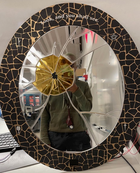
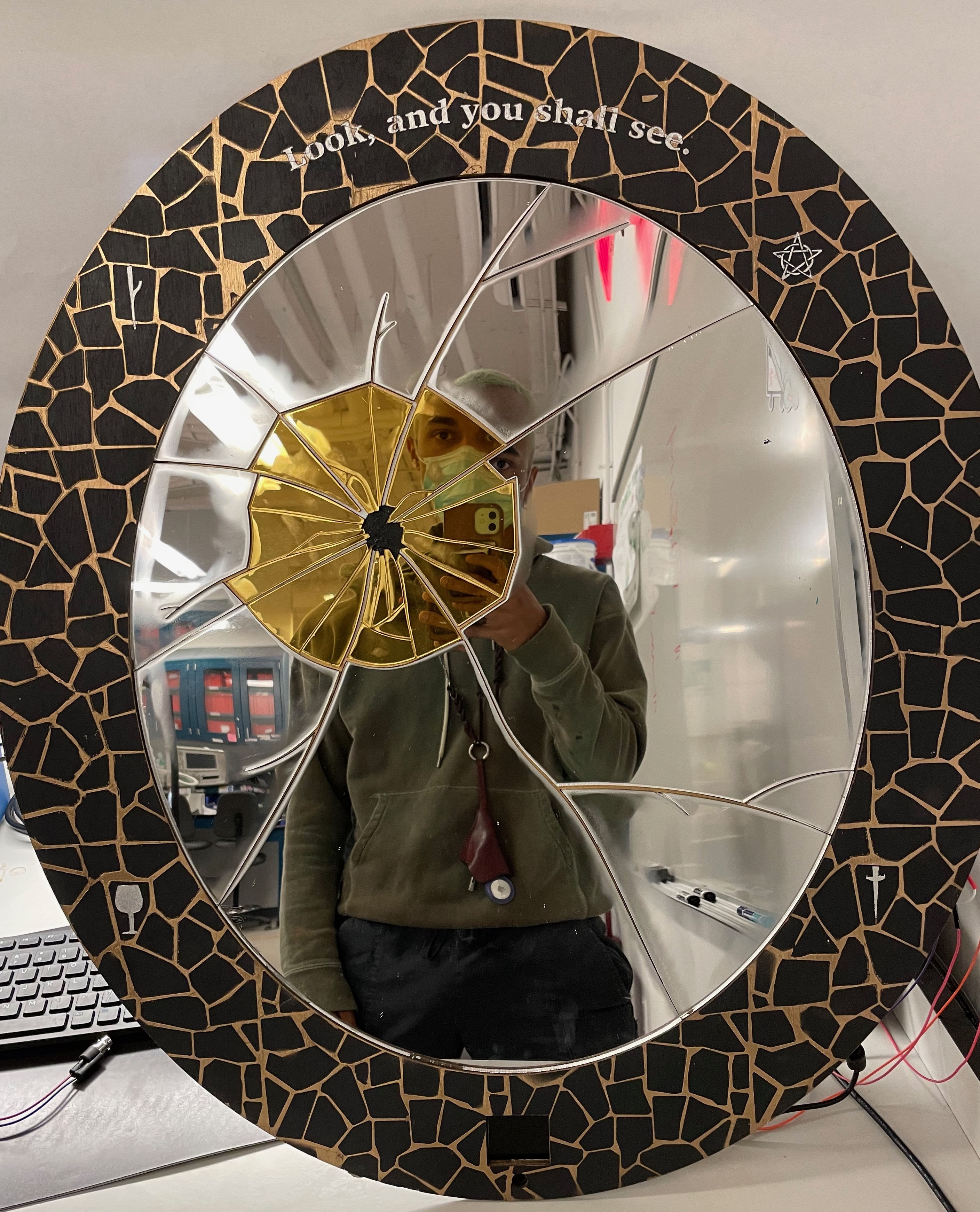
Final Product!
-
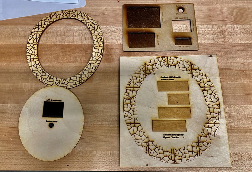
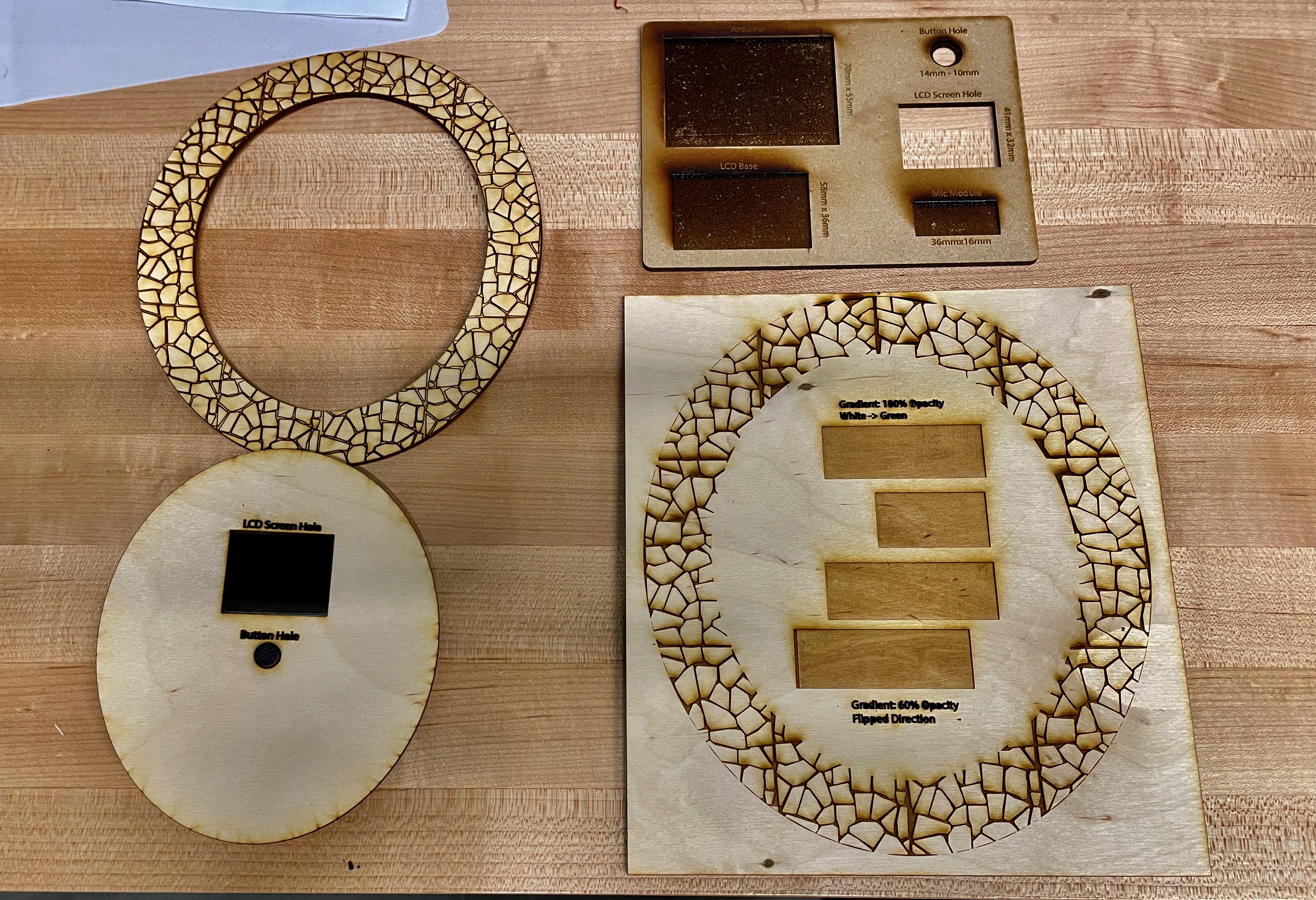
Aesthetic and module sizing test for prototyping
-
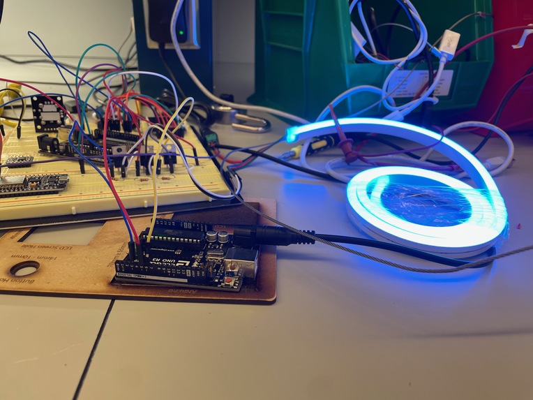
LED Color control testing, and integration with circuit.
-
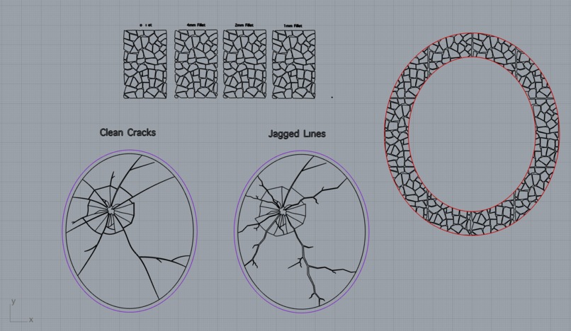
Potential Mirror designs in Rhino.

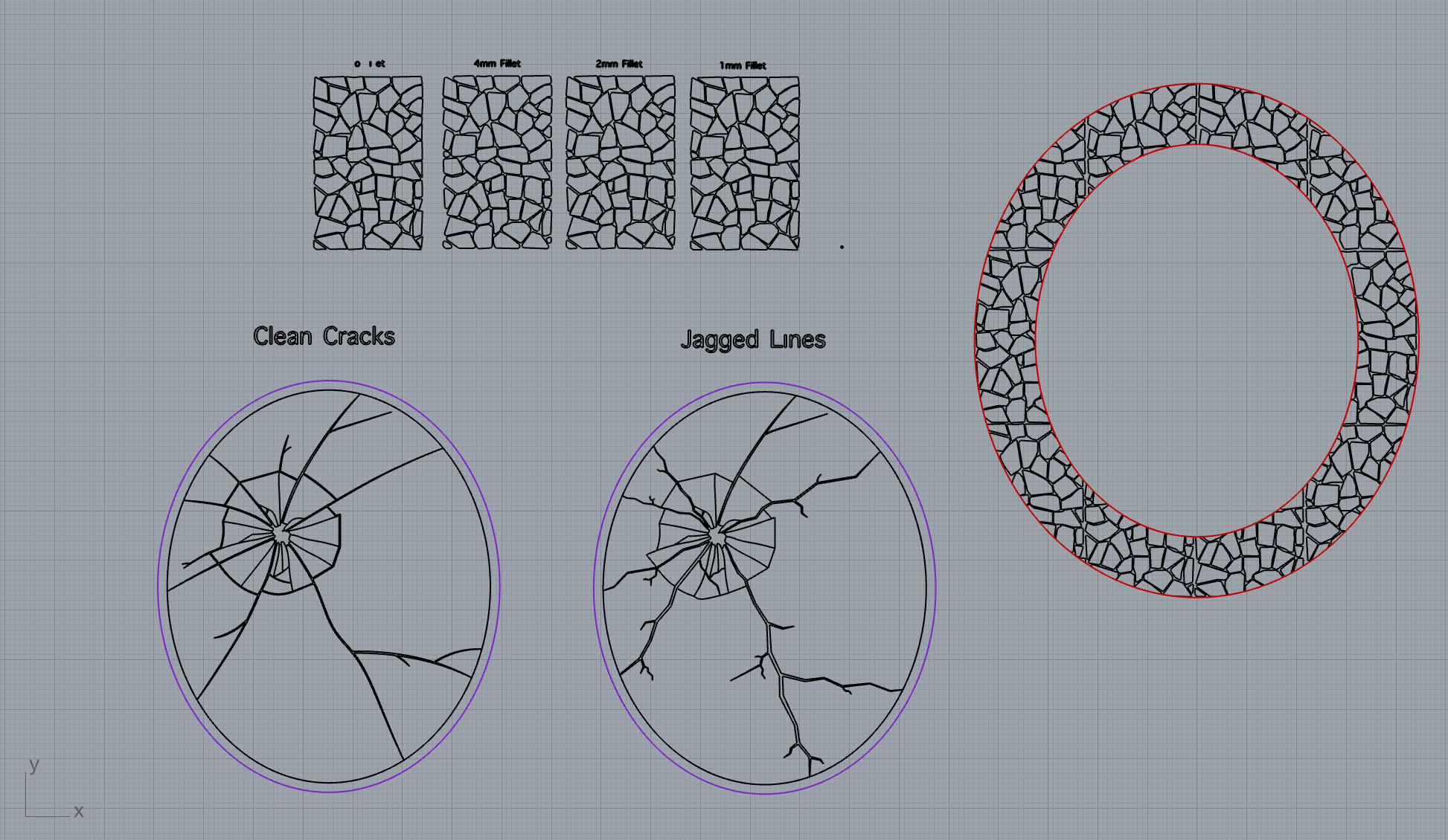
Inspiration
Everyone has their morning routine: mine always involves a mirror. It is the central way to connect with myself, and a visual aid to assist activities like dressing, affirmations, and haircare. The motivation is to create a central piece to my room that can elevate the aesthetic while assisting with the functions of my day. Something so important should be made smart!
What it does
Upon a wake command, which could be something as simple as a clap or as complex as a wake word, the mirror will “draw” a tarot card for the day and present the reading on an LCD screen. Ancillary components like colored LEDs or music might be triggered on power-up/down. The focus here is on integrating the electrical and physical components with a high degree of fit and finish such that it would elevate an existing space.
How I built it
This project required a multi-step design that included a fabrication side, and a software side. Anyka took lead on the software as the resident CIS major, while Cole headed up the fabrication given his experience in the design lab.
The physical fabrication wasn't terribly complex, but took time to iterate on and evolve into its final form. The concept cam from Cole's experience making puzzles with laser cut wood - essentially piecing together a base, frame, and set pieces to make one interactive 2D image within a wood base. The error was a similar concept driven by one major design constraint - the mirrored acrylic needed only came in 12"x12" size, so for a larger mirror they would take the form of "pieces" inside the frame. Given that we wanted to maintain aesthetic value, we worked around this by attempting to make the mirror look intentionally "broken", with many shards pieced together. Ideally, we wanted to elevate that idea by creating reflective distortion through inlaying the pieces at an angle.
Multiple mini prototypes were made to test components like the frame aesthetic, broken pieces fit, raster angle for piece inlay, and layer sizing. Each one provided new info to elevate the final version. For the final, I started working 3 days in advance to ideally finish within a day. The first day I spent the majority of my work hours in Adobe Illustrator, finalizing the file to be sent to the laser. I had to be very detailed with the crack design to make it look realistic, and provide enough spacing so the gold fissure would show through. Additionally, I had to test many settings on the laser with the lab tech to get the angled raster to work the way I wanted. After I had the base and pieces cut, I sent my frame file to be cut at the end of the day. It was a complex file that had many vectors; 20 minutes into the job the lab tech came out to tell me the frame caught on fire! Thank god I started early. I came back the next day to cut the final frame design (with a couple switches to prevent flames again), and put it all together. Simultaneously, Anyka was finishing the coding and we needed to get all electrical components off the breadboard. The rest of they day was devoted to soldering all connections onto a custom PCB for portability.
On the software side, we used only standard, built in libraries or ones provided through previous homeworks like that for the LCD setup. The code is a constant running loop that just checks if the wake word has been called and if it has, draws one or three cards based on what setting it is on. We utilized basic C functions like rand and time to get “random” numbers” to draw the card, with the seed being whatever the time was at bootup.
The microphone was read through the AC input pins and based on a calibrated threshold would trigger the actions. There was also a button input that could change the setting of whether 3 or 1 card was drawn.
For the RGB strip, we had to use non-PWM pins to control them as unfortunately there were not enough open to utilize given that we had to also control the LCD with a few of them.
Everything was integrated together, but the final had many jumbled wires and a couple components on a breadboard due to PCB malfunction. All-in-all, it came together quite nicely and the final project looked great and worked well at the same time!
Challenges I ran into
Anyka Using the non-PWM pins was very difficult as it significantly decreased the intervals of duty cycles that we could offer out of the pins since the overall frequency possible was also decreased by using timer interrupts rather than PWM pins. The final “rainbow” cycling was still functional, but not as smooth as standard rgb rainbow cycles can be expected to be since we had to trade color changing smoothly for non-strobing LEDs. Additionally, the tarot card graphics were not as detailed as initially hoped for because of RAM limitations on the arduino. However, given the remaining time in the project, we decided to turn our efforts to enhancing other parts of the project rather than implementing additional libraries or technologies to add storage.
Cole My challenges were mainly in fabrication, not design. There are always little things that pop up when making physical things. The frame fire, misalignment of frame and base, incorrect glue job, and warping along the acrylic all happened during the process. Some were solvable, some weren't. In the end, all issues were minor and the final was hacked together.
Accomplishments that I'm proud of
Anyka For the RGB lights, we used the timer’s output compare in CTC mode to interrupt the timer at a set frequency and use that as the baseline output frequency for the LEDs. This was a bit of a trial and error process since it was hard to nail down the perfect balance of smooth color transitions and not strobing the LEDs. Getting to our final result was very rewarding. Additionally, the layout of the LCD was quite detailed and a lot of pixel planning was necessary, so a lot of work went into finding the ideal layout down to the pixel and manually programming these into the LCD graphics library.
Cole I'm really proud of the details on my mirror. I will brag on some of them.
- The cracked aesthetic was quite tedious and hard to do. In the fissures I painted the base gold so they shone through.
- The frame pattern was designed and painted by me, using laser techniques I've been learning over 2 years.
- The aesthetic integration between mirrored acrylic color (silver, gold), frame color (black, gold) and fissure color (black, silver, gold) was all intentional and visualized with the inception of the project.
- I learned to use Illustrator at a high level through this project, picking up a new skill.
- I achieved near exactly what I envisioned when I thought of the project.
What I learned
This project really enhanced my understanding of using timer output compare and making PWM signals out of non-PWM pins as well as general knowledge of all the topics we were able to incorporate into the final result. Utilizing concepts learned in lecture and practiced in labs, we were able to take them further in this project and truly understand what each command was doing.
We learned significant amounts during this project. There was new software and modeling skills picked up, as well as a continuation of how an LCD screen works, and an analog RGB strip. These were all new ideas for us, and generally we learned the process of making and integrating a physical product at a high level.
Built With
- arduino
- rhino

Log in or sign up for Devpost to join the conversation.