Inspiration
In recent years, with the development of biological electrical signals, more and more technologies are used in life and medical applications, such as BMI, CMI, EMG, etc. At the same time, with the increasing number of people with limited mobility, there is a growing concern about how to ensure their living convenience. Under these conditions, the use of bioelectric signals for the control of the trolley is promising for a wide range of applications. In an indoor environment, the trolley can help people with limited mobility to pick up packages or takeouts. In the outdoors, the trolley has certain obstacle avoidance functions to help blind people reach their destinations safely. Compared with a four-wheeled car, the self-balancing trolley has a wider application scenario. Due to the smaller size of the body, it is easy to carry and can pass through more narrow areas. In this case, we want to make an interesting attempt to combine EMG signals and a self-balancing car to help people with limited mobility to pick up packages and have some obstacle avoidance functions.
What it does
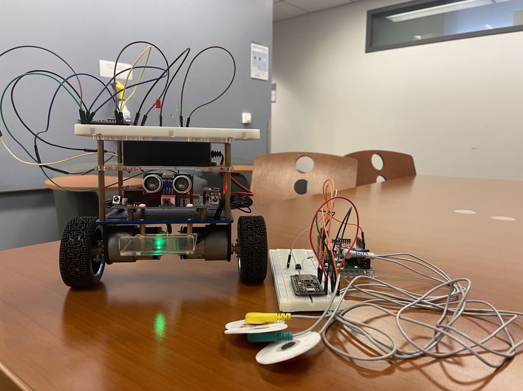
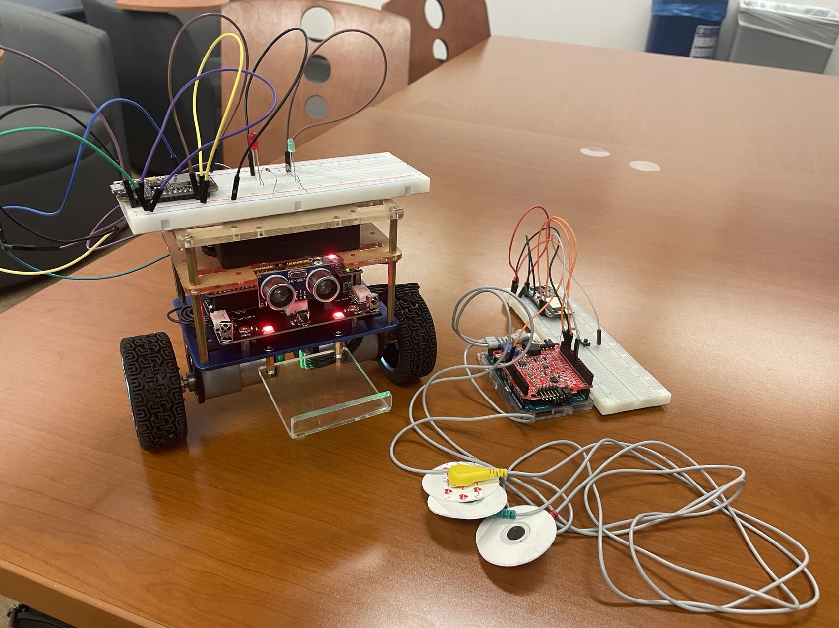
sEMG signals show huge potential in implementing control systems of mechatronics devices, and small muscle movements can generate enough sEMG signals to achieve desired control operations. In this project, we design and implement an intelligent self-balancing trolley controlled by EMG signal. We divided the task into three parts: 1. EMG signal acquisition and real time control via FFT. 2. Trolley balancing and movement. 3. Wireless communication between two ESP-8266. The trolley can eventually move forward, backward and standby via EMG signal control. In addition, it can perform some special functions, including: Obstacle Avoidance and Auto Follow. This project is basically successful, but it still has some areas for improvement that we can try in the future.
How we built it
We divided the task into three parts: 1. EMG signal acquisition and processing at real time. 2. Trolley balancing and movement. 3. Wireless communication.
Real time processing EMG signals
The electromyographic signal (EMG) is the temporal and spatial superposition of motor unit action potentials (MUAP) in numerous muscle fibers. Surface EMG signal (SEMG) is the combined effect of superficial muscle EMG and electrical activity on the nerve trunk on the skin surface, which can reflect neuromuscular activity to some extent and is the electrical signal accompanying muscle contraction. In order to meet the needs for real time EMG signals processing, the microcontroller has to be tweaked so we can capture, process and output analog EMG signals. We used a Real Time DSP algorithm to obtain the analog data. The EMG data can flow into the microcontroller by using ADC. Setting sample frequency to 200hz so that we can select the slide window. Once the input signal has been sampled and processed by FFT, one way to convert it back to analog is to use the embedded PWM mechanism that is avail- able in some of the output pins of the microcontroller. Finally, we can obtain five peak frequency thresholds, which are the maximum values in the select window. By using these feature values, we can set different values to recognize different gestures . In our case, interrupts are of extreme value as they are the low level structures that allow us to execute code with a somewhat fixed frequency. Below we can see the code for the interrupt service routine (ISR) DSP controller function.
Trolley balancing and movement
(1) Moving Control DC motor is inductive load with large current (load with inductive parameters), while the IO of Arduino Nano, the single chip microcomputer we use, has weak load capacity (i.e. output current capacity), and its driving capacity is not enough to supply enough electric current for motor to rotate. Therefore, we choose to use TB6612FENG motor driver chip. In this trolley, MOTOR A: PWMA is connected to D5, AIN1 is connected to D7. MOTOR B: PWMB is connected to D6, Bin1 is connected to D12. For EMG control, EMG HIGH is connected to D13, EMG LOW is connected to D11. When the motor rotates, the input signals of AIN1 and AIN2 are always opposite. So in order to save IO resources, we add SN74LVC2G14 Two-Way Schmitt Trigger Reverser, the input terminal is connected to AIN1, and the output terminal is connected to AIN2, so that the level state of the input terminal and the output terminal is always inverted. It is the same for Bin1 and BIN2. In order to achieve the balance function in the later part, we need to obtain the motor speed and rotation direction, so we also need to drive two hall sensors on the motor to achieve the speed detection and rotation direction detection function. or EMG moving control, restricted by the available ports on Arduino Nano, we reuse the Ultrasonic Trig Pin (EMG-LOW) to realize Forward, Backward and Standby (Stop) control mode. The results showed that we can successfully use an EMG signal to control the trolley move with a tolerable delay. However, for the RightFront and LeftFront mode, such a delay may cause the trolley to lose control signal for some time and then become unstable. Therefore, a multi-channel EMG input and a powerful chip may solve this problem. (2) Balanced Control In this part, we use the MPU6050 module to measure the values related to the attitude changes, such as the angle value and the angle speed value, and then adjust and control the driving motor accurately through the PID control algorithm, so as to realize the balance control function. The core idea of balancing the vehicle is "dynamic stability". The attitude data is obtained by MPU6050, and then the motor is adjusted by using the control algorithm to achieve the balanced effect. We can divide the trolley motion control task into 3 basic control tasks.
- Balance Control (Vertical ring): To keep the trolley maintaining the upright balance by controlling its forward and reverse motion.
- Speed Control (Speed ring): To control the speed by adjusting the inclination of the trolley, in fact, it finally evolves to control the wheel speed by controlling the ratio speed of the motor.
- Direction Control (Turning ring): To control the direction change of the trolley by controlling the rotational differential between the two motors. The three kinds of control (upright, speed and direction) of the balanced vehicle are finally superimposed as the control quantity of the motor output voltage. Of the three controls mentioned above, the vertical control is the key, so the adjustment speed should be very fast. From the point of view of the upright control of the vehicle model, the other two controls will become its interference, so the speed and direction control should be as smooth as possible to reduce interference with the upright control, so its relative adjustment speed should be set to slow. Next, the realization of the three controls is mainly achieved by the traditional PID feedback control, PID is proportional, integral and derivative. When a certain physical quantity needs to be "stable" PID will be of great use. Because the accelerometer and gyroscope of MPU6050 have their own advantages and disadvantages, there is no accumulated error in the acceleration value of the three axes, and the inclination angle can be obtained by calculating tan(), but it contains too much noise (because the acceleration will be generated when the object to be measured moves, and the vibration will be generated when the motor is running), so it can not be used directly; the gyroscope has little impact on the external vibration, with high accuracy, and it can not be used directly by calculating tan(). The angle of inclination can be obtained by the integration of angular velocity, but there will be accumulated error. Therefore, in order to obtain the accurate obliquity and angular velocity values, we need to use the Kalman filter.
Wireless communication
ESP-NOW ESP-NOW is a “protocol developed by Espressif, which enables multiple devices to communicate with one another without using Wi-Fi. The protocol is similar to the low-power 2.4GHz wireless connectivity. The pairing between devices is needed prior to their communication. After the pairing is done, the connection is safe and peer-to-peer, with no handshake being required.” This means that after pairing a device with each other, the connection is persistent. To communicate via ESP-NOW, we need to know the MAC address of the ESP8266 receiver. Here’s what we should include in the sender sketch: 1. Initialize ESP-NOW; 2. Register a callback function upon sending data – the OnDataSent function will be executed when a message is sent. This can tell us if the message was successfully delivered or not; 3. Add a peer device (the receiver). For this, you need to know the receiver MAC address; 4. Send a message to the peer device. On the receiver side, the sketch should include: 1. Initialize ESP-NOW; 2. Register for a receive callback function named OnDataRecv. This is a function that will be executed when a message is received. 3. Inside that callback function save the message into a variable to execute any task with that information.
Challenges we ran into
We did meet some problems when implementing the Real time processing EMG signals. At the beginning, we expected to use more accurate FFT sampling points to implement high accuracy Real-Time DSP algorithms. However, when we connected the arduino with the trolley via ESP8266 module, we found that the control signal had extremely high delay since it took a lot of time for the Server to calculate the results. So we chose lower sampling points FFT and just extracted several peak frequencies to simply classify different gestures. The advantage of this method is that the response time of the trolley becomes faster, but the classification accuracy is lowered, especially when we change gestures. In the future, to balance the delay-accuracy tradeoff, a time domain feature will assist to improve the performance with a low computational cost. Furthermore, a multi-channel EMG input and a powerful chip can provide opportunities to complete more control modes like RightFront and LeftFront modes.
Accomplishments that we're proud of
We completed our project as expected. We ensure the balance of the trolley by collecting the speed of the servo. Adding with the PID algorithm and Kalman FIlter, the self-balancing ability of the trolley performed very well. One channel EMG signal can control the trolley, just use 2 pins to realize this module. By using the ESP-NOW protocol, the trolley can be communicated with devices in a good range. Indicator lights on the trolley allow us to understand the current control mode at this time.
What we learned
We learned a lot in this project. First, we know a way to realize real time digital signal processing. By using the ISR to read data, ensuring that the data can be captured in real time when processing. Second, using the MPU6050 module to measure the values related to the attitude changes. Combine with the PID algorithm and Kalman Filter, ensuring the trolley can self-balance. Finally, short-range wireless communication to multiple devices using ESP-NOW. It is a short data transfer, connectionless and fast communication technology that allows low-power controllers to directly control all smart devices without connecting to a router.
What's next for Self-balance Car with EMG signal
Further development: robotic arms and route planning can be expanded based on our project, and can implement more tasks.

Log in or sign up for Devpost to join the conversation.