-
-

-

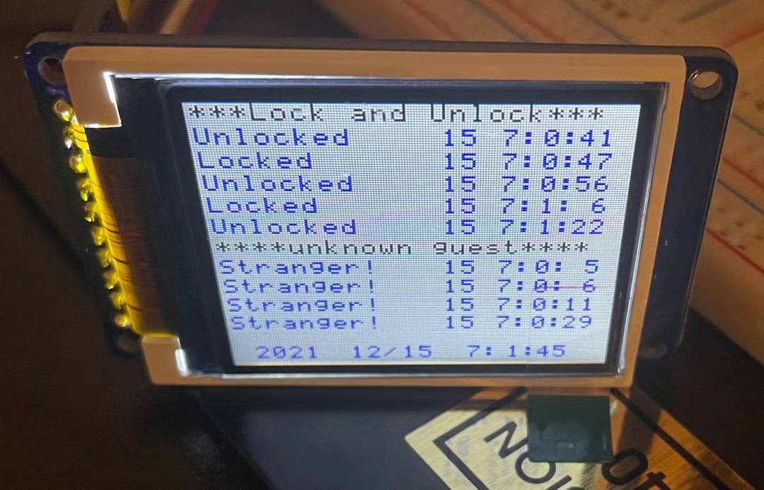
Guest History
-
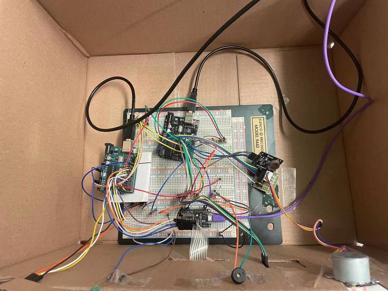
Circuit

Abstract
Nowadays, technology improves the quality of people's lives with convenience and safety. In this project, I will be demonstrating a keyless safeguard lock system. Users can unlock it with passwords or cell phones. I can also detect if anyone has tried to approach the lock, and record it with the time. I will use a screen to let the user search if anyone is trying to approach the lock and when the lock has been unlocked. Users can also read the message in the phone app to know if anyone visits.
Motivation
While we are using the physical key in our daily lives. We may be facing many different problems. Here are three major problems:
- Difficult to find the right one if you have too many.
- If you lose it, then your property is at risk of getting stolen.
- physical keys take too many spaces The purpose of my project is to solve this problem. I will use passwords and phone apps as methods to unlock the door. So a big heavy physical key is no longer needed. I will also add some interesting functionality. When you are on the way to work, many people try to recall whether they lock the door or not when they leave. But, they are too far away from home, so it's difficult to check their doors. If they can remotely lock or unlock the door, this problem can be solved. Also, many people have worried about if any unknown guests visited their home. I will use a small digital screen to let the user check who was trying to approach the gate, and when it happens. The lock and unlock history will also be available to look up through the screen.
Methodology
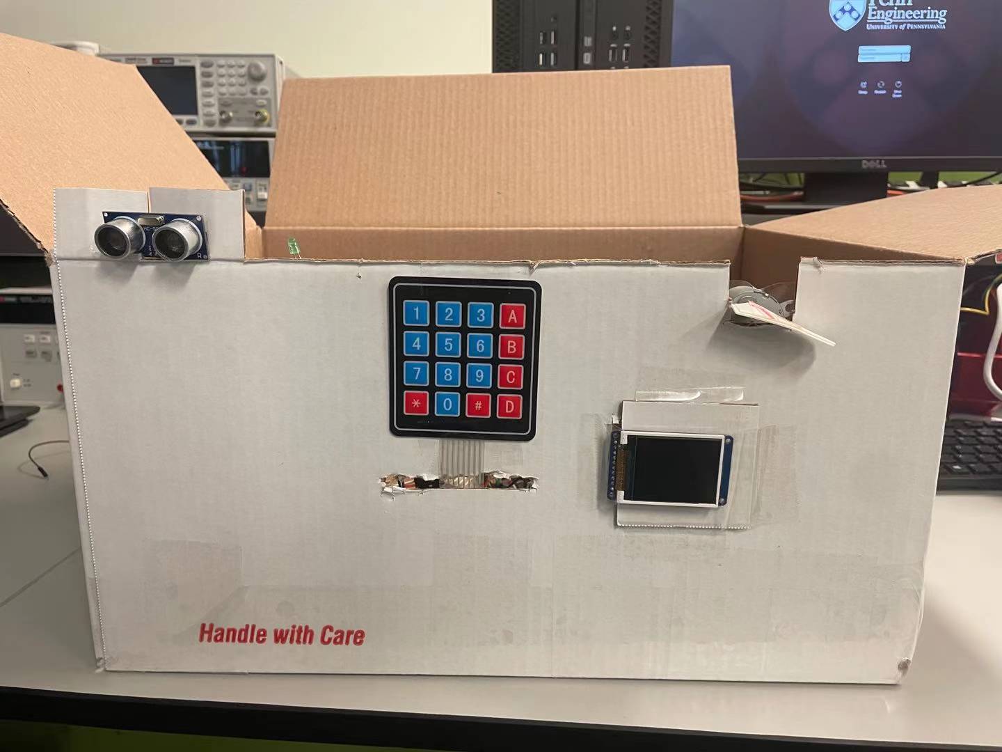
I will use two Arduino to approach my project. The Arduino 1 will receive keypad and ultrasonic sensor input. The ultrasonic sensor will detect if anyone is trying to approach the lock. We will need a 4 by 4 keypad to enter the password input and send commands and control to Arduino 2. The buzzer will be used to give input feedback. After Arduino 1 processes the input, it will send commands to Arduino 2. Arduino 2 will control the LCD display and stepper motor give feedback. The Arduino 2 will also read the current time from the real time clock, and record it when needed. The guest's approaching signal will also be sent to ESP8266, and it will send the guest alert to the phone app. ESP8266 will also send the signal to Arduino 2 to control the lock or unlock state.
For the keypad, I found it is not necessary to use any library.
There are 8 pins on the keypad. I will set 4 pins as output, and 4 pins as inputs. In the beginning, all 4 outputs(columns) will be set to high, and the 4 inputs(rows) will all be set to high. Then I will set only 1 output to low, and other outputs remain in the high state. Then check which input changed to low state. For example, if only C1 in the graph is set to low, and C2, C3, and C4 remain high. If we press the button at '1', it will connect to the R1 input and set it to low. By checking the state of R1, R2, R3, and R4, we can find out if “1, 4, 7, *” have been pressed. Then I will repeat this process 4 times for each column(“2580”, “369#”, “ABCD”). Then I can locate which button is pressed. Also, adding appropriate delay to the process is necessary. We only want to read one character when the button is pressed once.
I used a char array with a length of 4 to store the passwords inputs. The passwords will only accept numbers. I used a for loop to get user input 4 times, then compared to the correct passwords. The correct passwords are 4 char values that can be changed. Then, the array of char will be reset to null, and the system will loop to the for loop again.
If the password input is not numbers. I use if statements to recognize them and send signals to Arduino two. The delay has to be long enough so that the Arduino two can successfully receive the commands. After completing the task, the loop and the password will be reset. Here is the table of commands.
The buzzer is controlled by PWM in the Arduino one, the frequency can be controlled by changing the OCR0A value. It is initially set to 0. I want the buzzer to give some feedback when any button on the keypad is pressed. If any button on the keypad is pressed, OCR0A will be set to 58. This means the frequency will be set to 2093 Hz. After a very short delay, the OCR0A will be set back to 0. If the password is incorrect, the OCR0A will be set to 58 and delayed for 3 seconds. If the password is correct, the OCR0A will be set to 59, 62, 70, 78. This is to tell the user the password is correct.
When a guest is detected, the Arduino one will send a signal from PB4 to Arduino two PD7. After Arduino two receives the signal, I will record the time by reading the RTC. Then, if the current time is 5 seconds above the recorded time, Arduino two will send a signal to ESP8266, then ESP8266 will turn on the LED and send a message to the phone.
For the phone lock and unlock, when the button on the app is pressed. ESP8266 will send signals from PIN2 and PIN4 to Arduino two. If Arduino two detects the signal is received, it will open or unlock the door.
For the guest history. I define the current time as uint16_t values. I will be refreshed in the main while loop. I convert them to arrays of char and print them out at the bottom of the main screen. I used two 2D arrays of char to store the unlock history and guest history. I defined some addresses for every cell of the 2D array. When it’s needed to record the time, the current time will copy the value as char type to the desired address. I use pointers to point to where this address belongs to.
For the stepper motor part, I set it to move 256 steps each time to twist 180 degrees.
The ESP8266 will receive signals from Arduino two in order to send messages to the phone. My breadboard has lots of wires and it is really crowded, so I don’t want to use the logic shifter here. Instead, I used a voltage divider. With two 3.2 Kohm resistors, the output voltage converted to around 3.3V. I measured the voltage in the lab to make sure it's safe to use.
Results
My result went very well. My keypads can receive correct inputs, record the passwords and send the commands correctly. The command is smooth and accurate. My buzzer and ultrasonic sensor worked well with no issues. And the stepper motor can lock or unlock the door smoothly. I can control the lock with a phone app with no error. And the phone can receive the message sent from NodeMCU correctly, but with some delay. The RCT works well. My LCD can display the accurate current time and guest history. All the expected functions are accomplished.
Built With
- buzzer
- keypad
- lcd
- rfid
- stepper
- ultrasonic

Log in or sign up for Devpost to join the conversation.