-
-
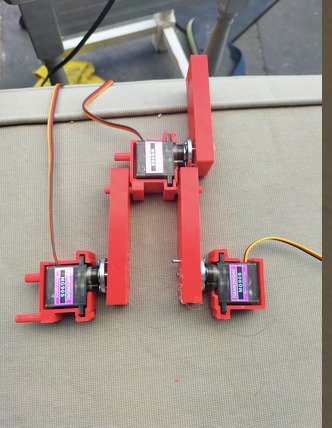
An simple design to an robotic arm that uses a intuitive and efficent method of inverse kinematics.
-
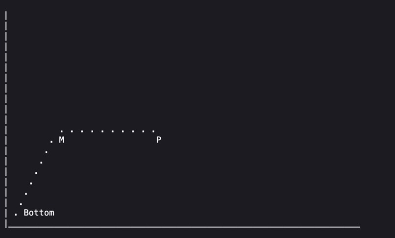
Reference image
Inspiration
It started when I was watching MIT maker portfolio videos. I kept on seeing the term "Inverse Kinematics" being thrown around which sparked my curiosity. However when I tried to research it further I saw very complicated math that were not intuitive, easily learnable or efficient. A lot of robots used a approach that uses matrices and co ordinate transformations inside them. I decided I could make a simpler, more efficient, intuitive and easily learnable method instead. I limited my information only too simple high school trigonometry using concepts such as "SOH-CAH-TOA" (Sine= Opposite/Hypotenuse, Cosine = Adjacent/Hypotenuse etc...) and the cosine rule. I also in cooperated properties of triangles to find a workaround to projection angles.
What it does
This robotic arm moves based on co ordinate input with a very simple, teachable and intuitive inverse kinematics method that also uses less processing power as it uses much more simpler math.
The method:
(Check image as reference)
First we need to take an co ordinate input and calculate the distance between it, so we are calculating the distance between Bottom and P. This is pretty straightforward and can be done with the distance formula. Suppose you pick the point (3,4), to calculate the distance between the origin (the base) and this point it's simply $$D^2=x^2+y^2$$, where D is distance, and x and y are the side legnths, but since we are starting from the origin, the x and y are zero. For our example the equation would result to $$3^2+4^2$$ which would be 25. Now that we know d^2, we need to square root that, so the distance in the end is $$\sqrt{25}$$ which is 5. Now that we know the distance we can move on to the next step.
You see the middle angle named m? Now, we need to calculate that. We can calculate this by using the cosine rule which is $$a^2=b^2+c^2-2bc·cos(A)$$ since we want to angle, we can rearrange the formula to $$cos(A)$ = $(b^2+c^2-a^2)\over2bc$$. (See picture to get what I'm talking about), now we can use our distance a, and our x and y co ordinate to get b and c and we can solve for the angle
Now some tricky parts come in, you might have learned that when using sine or cosine etc they are systematical so there are 2 answers. If you don't know this search it up, but basically cos(10)=x and cos (170) can also be X. This just means there are two possible answers to the problem, which is why with the answer we get we store it in one variable, and we do cos(180-A) to get our second possible answer and store it in our second variable.
Finally we need the base angle, instead of calculating projection angle I use properties of triangle to find out the base angle. First lets find the normal base angle assuming the robot was a straight line, we can do this with $$Angle=$$ $$tan^-1$$ $$x\over y$$, where x and y and the side lengths, but in this case the co ordinates. Now this angle ignores the bend in the middle arm and to counter act the bend we can do some simple math. Since this robot has both arm lengths the same we can make an isosceles triangle. With basic math we can find the other two lengths, now if we take our tan angle and subtract the side angle with it we have our base angle that includes the projection.
Finally (last one), we need to calculate the most efficient angle. Remember how we stored two angles for cosine, we now test both of them, by adding the absolute value of solution one to our base angle, and the same with solution 2. the solution that provides the smallest number is used.
How we built it
I built it using a custom cad case, however I didn't over complicate it making each and every component easy to see, understand and recreate, and fix. Most arms are enclosed which leaves people wondering how the motor gears mesh with the design to move, however by creating an open design I make sure it's easy to see understand and improve. (Additionally everything is open source on git-hub with a detailed read me about this project)
https://github.com/SSLTunezz/Teaching-a-robotic-arm-maths
I used easily accessible motors, which are the servo mg90s, that don't require PID values, for example you can just say ServoWrite(xyz) where xyz is an angle and it will move there, further contributing to the easily understandable and intuitive goal.
The assembly was very easy and takes only around 5 steps, it's plug and play with minimal setup required before hand apart from wiring, which can be simplified if necessary.
Challenges we ran into + ## Accomplishments that we're proud of
It was very hard to make a method of inverse kinematics that was limited to basic trig functions such as sine, cosine, and tangent. This meant I had to think of a way around the formula. For example at some point the only thing between me and my answer was the projection angle formula, however since this would be not intuitive method, I instead had to find a work around with angles of a triangle and it's properties. For example I used the fact that my arm forms an isosceles triangle to angle hunt and find the right answer. This took a while to brainstorm but I am very proud of it
What we learned
I learned how I can simplify complex methods into simpler ones, since this was my first Hardware integrated with software project, I learned how they come together to form an system, and since I am usually not a coder I learned a lot of python and cpp
What's next for Robotic arm
Right now this arm method is applicable for 2 degrees of freedom, which means it has two motors. I plan on extending this to three which will introduce some challenges and will require a new approach but I am really eager to extend this further. Additionally I plan on adding a camera integration that uses open cv to get co ordinates of objects to pick up. I also plan on adding a gripper onto the arm which will make it more applicable in real like
Built With
- arduino
- motors
- servos

Log in or sign up for Devpost to join the conversation.