-
-
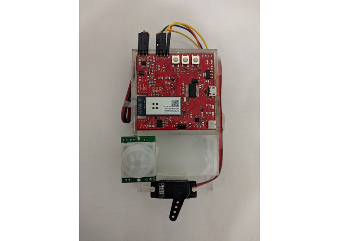
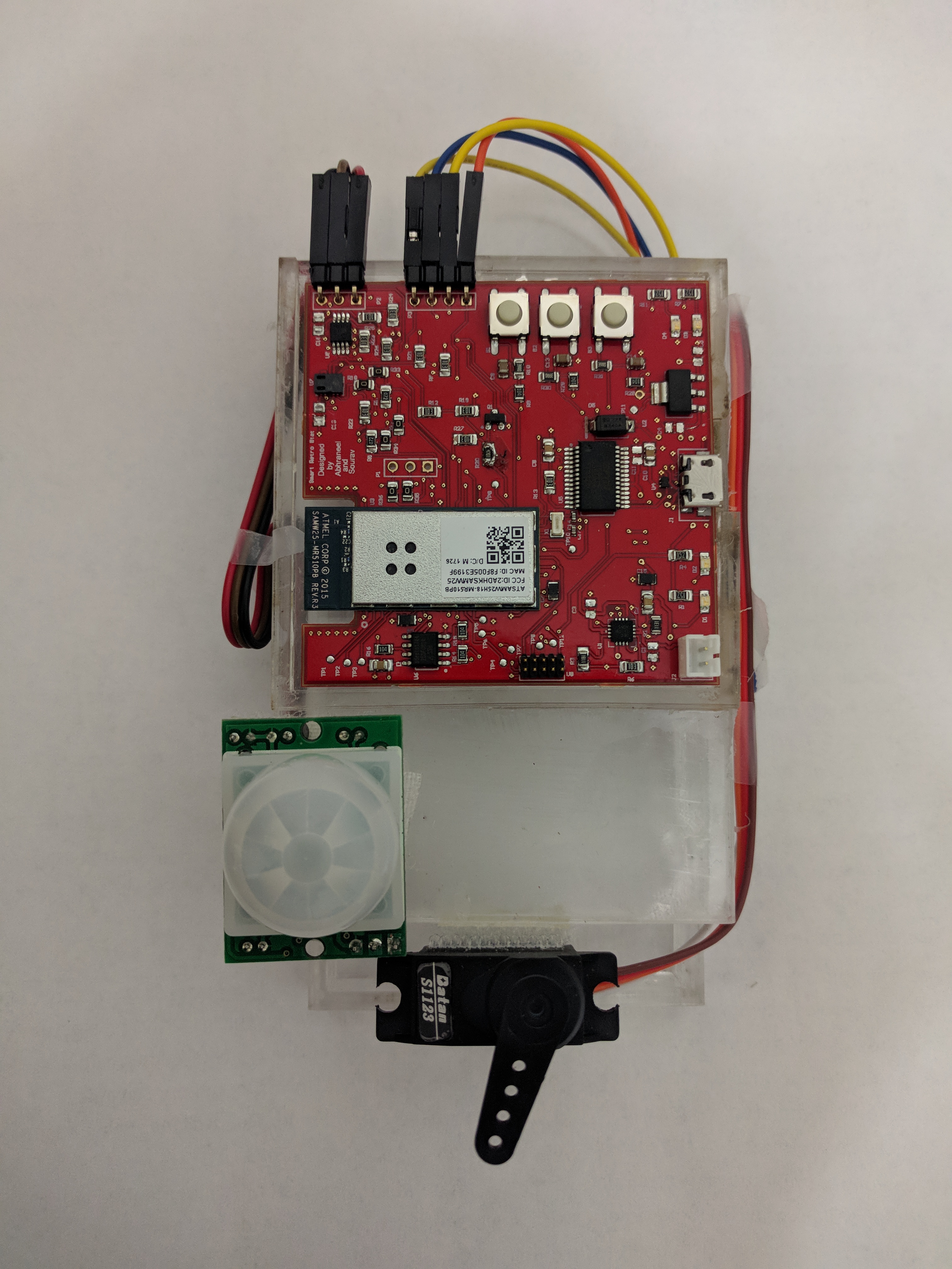
The device
-
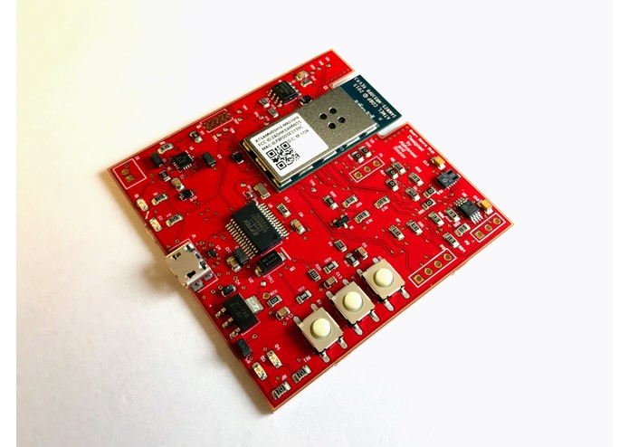
PCB front side
-
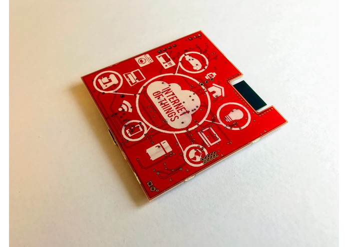
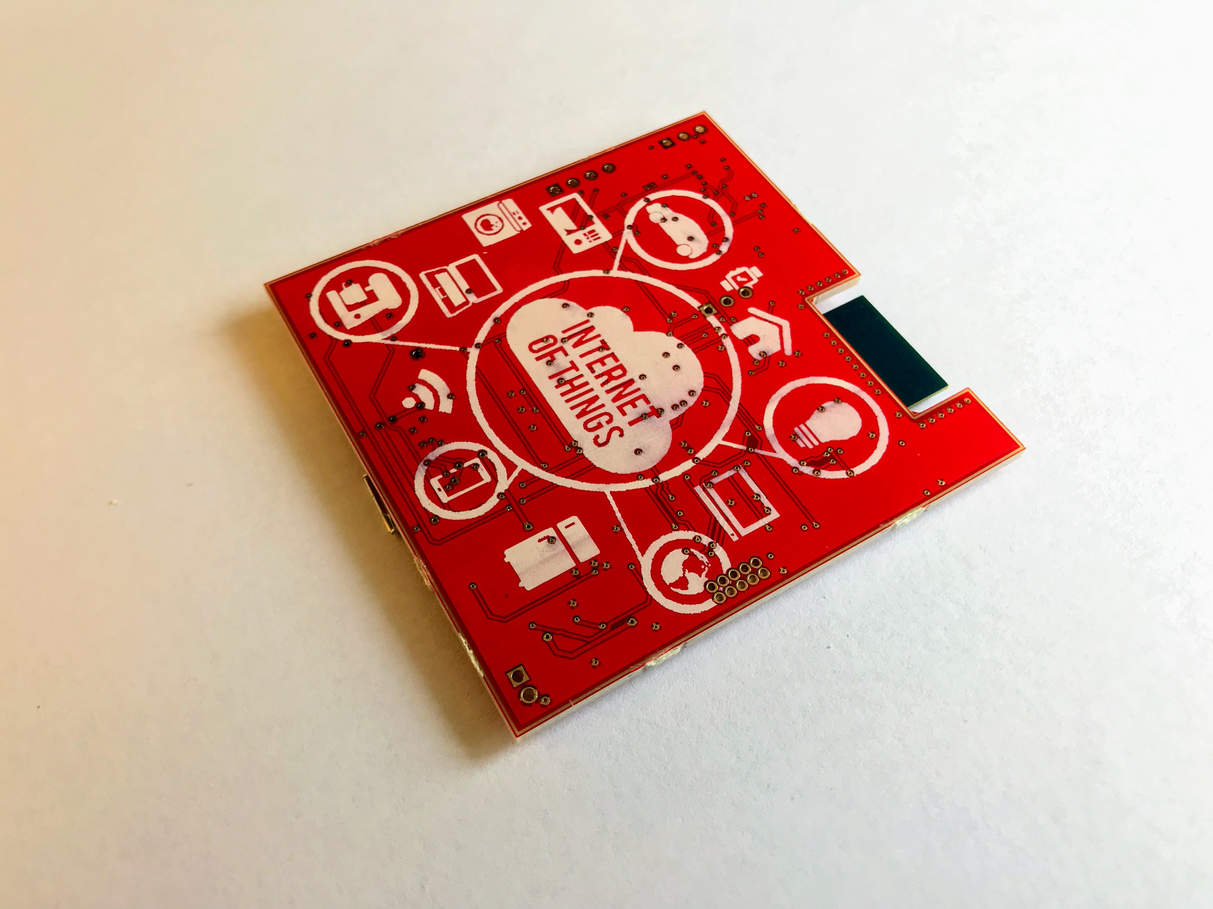
PCB back side
-
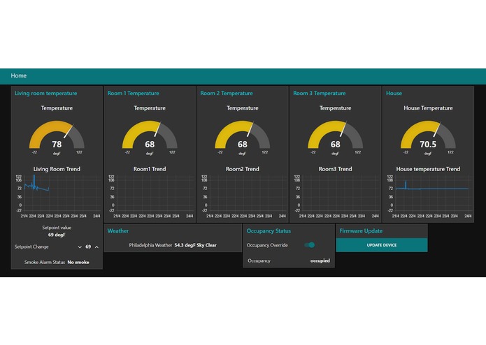
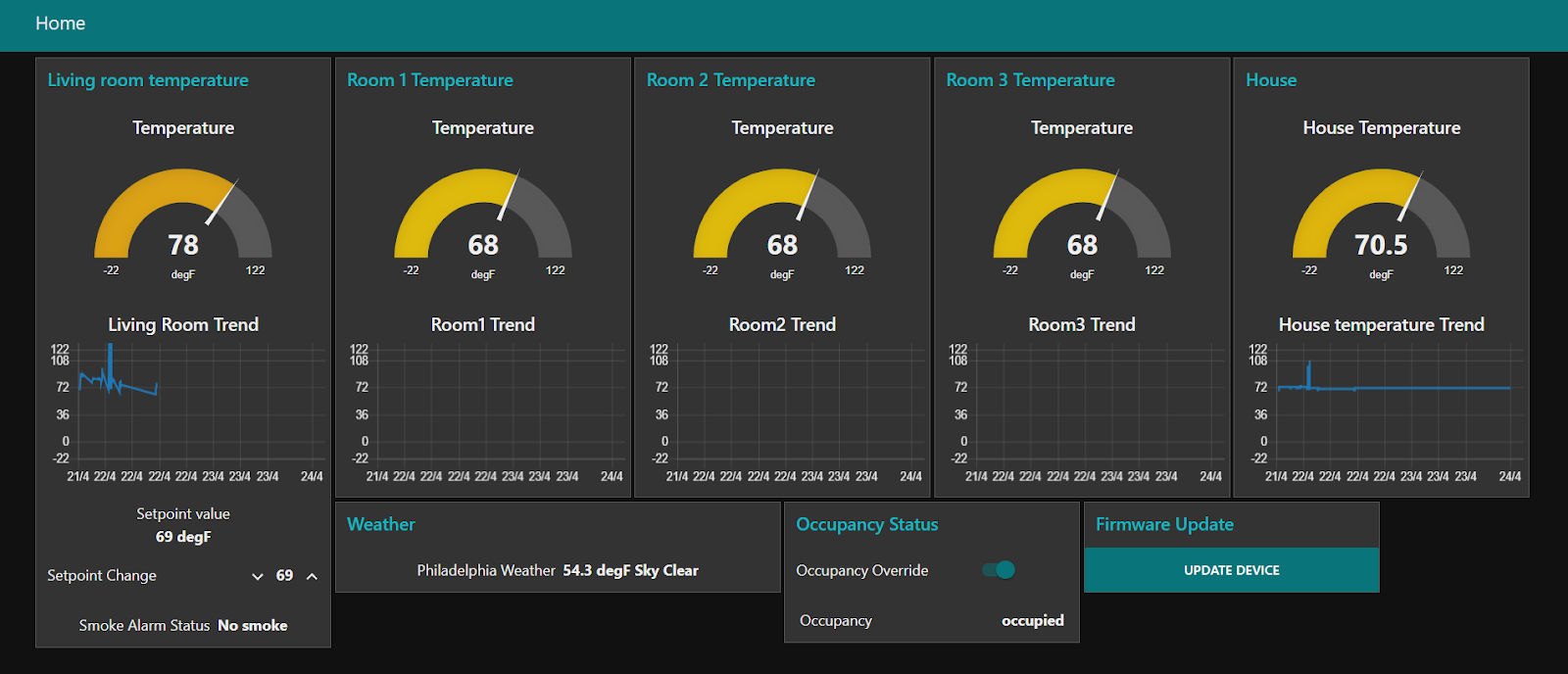
Cloud Console
-
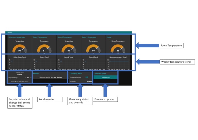
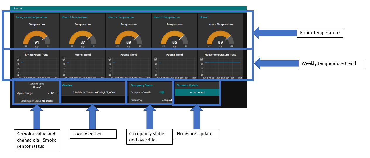
UI_functionality
-
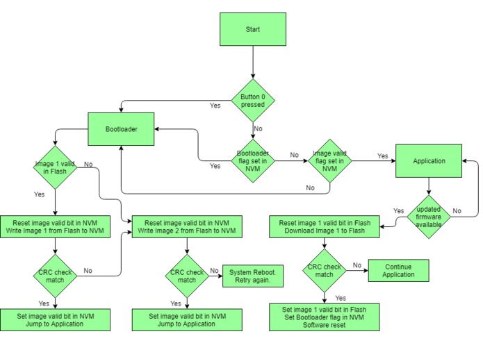
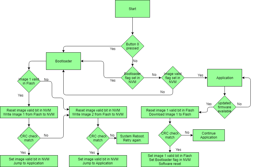
Bootloader flow diagram
-
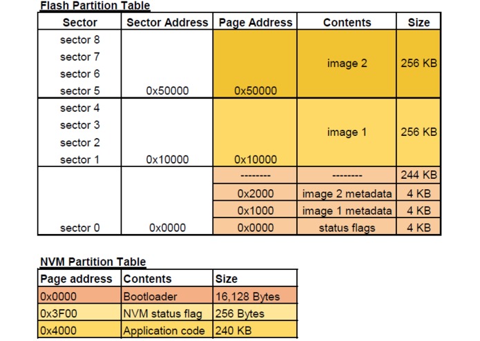
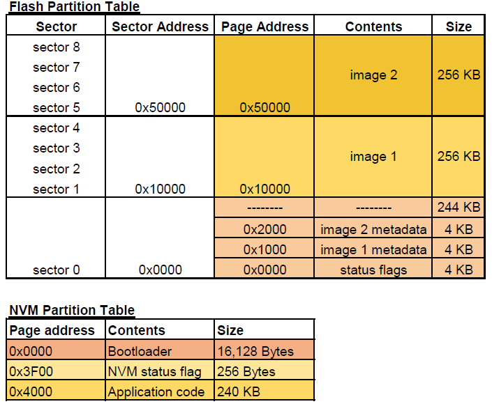
Memory Partition Table

Purpose of the Project
Retrostat is a device that can be easily fit on top of a mechanical thermostat. Retrostat is not a thermostat itself but would transform your existing thermostat to a smart cloud-connected device.
Project Background
The concept was designed based on a problem that we usually face at our home with our old thermostat which doesn’t function in the way it should as the mechanical sensors have become inaccurate. Furthermore, the thermostat keeps on functioning when there is no occupancy, consuming more amount of energy and cannot be remotely operated.
Killer Features
- Easy installation.
- Supports real-time temperature monitoring and setpoint adjustment through cloud dashboard.
- Supports temperature data collection from multiple rooms for generating average reference temperature.
- Supports occupancy detection and instant alert for fire/smoke through SMS.
- Easy on the go setpoint lever calibration for the user.
- Over the air firmware upgrade with robust error handling.
- Supports voice commands through Alexa.
Interaction with the device
- Webpage created with
NodeRed APIand hosted onIBM Bluemixcloud allows the user to monitor the living room temperature where the device is placed and the temperature of 3 other rooms. The temperature trend of individual rooms and also the average temperature of all rooms can be monitored. The user can change the temperature setpoint for the thermostat and also monitor room occupancy. Smoke/fire alert is also provided through a popup message on the webpage and instant SMS on phone throughTwillo. A firmware upgrade check can be triggered from the webpage. - Other than the cloud interface, the device also supports query of present room temperature and changing temperature setpoint through
Alexavoice commands. - ### Button Functions
Button0: Resets the device.Button1: WhenLED1is off, by pressingButton1the device enters setpoint lever calibration mode. This is signaled byLED1fading. Setpoint lever should be moved to it's maximum and minimum position. On pressingButton1again, the device exits calibration mode and records the maximum and minimum position of the setpoint lever.Button2:Button2is kept reserved for future improvements. Presently on pressingButton2,LED2would glow.
Sensors Used
MCP9808: On-board Temperature sensor over I2C, Supports window threshold based interrupts.CCS811: On-board Air quality and gas sensor over I2C, Supports threshold based interrupts.PIR Sensor: External module for occupancy detection over single GPIO.
Actuator Used
Analog feedback servo motor: Connected to the setpoint lever. Analog feedback used for getting present servo position.
Other notable components
ATSAMW25: Wifi module with on-board cortex m0+.AT25DF081A: 8MB SPI Flash memory.BQ24075TRGTR: Single cell lipo charger.FT232RL: USB to UART converter.AP7361: 3.3V LDO.TPD4S012: USB ESD protection.
Bootloader operation
The bootloader is responsible for flashing the downloaded updates from Flash memory to internal NVM. Image integrity is verified with CRC32 checksum. Before any kind of memory write the corresponding image validity bit is reset and the bit is only set after the write is successful and Checksum is verified. This handles the case of power-off/brown-out/reset in between a write. More on bootloader operation in the attached flow diagram.
Cloud connection
The device communicates to the cloud over MQTT protocol. The device sends the present temperature data in Fahrenheit, the occupancy status and the smoke sensor status. It receives the temperature setpoint value and firmware upgrade trigger from the cloud.
Other notable Hardware and Firmware features
- The firmware is modular and completely event-driven. All actions are interrupt based which save CPU cycles and provide maximum battery throughput.
- The
servo motordraws a significant amount of power for holding it's position even when it is idle. Therefore, we have added the mechanism to turn on the servo when a new setpoint command arrives, allow some settling time, and then turn it off to save power. - We put the
Flash memoryto sleep after every read/write operation and protect the accessed sectors after data manipulation in order to prevent unwanted overwrites. - For configuring the
Temperature sensorinterrupt, we read the present temperature as a float value and set the upper and lower interrupt threshold to the ceiling and floor value of the present temperature. Temperature data is only published to the cloud if there is a temperature change within 1 degree or more. Smoke sensoris used in a similar way as the temperature sensor. The only difference is that there is only one boundary interrupt threshold instead of a threshold window.- The digital output from external
PIR sensor moduleis also used as an external interrupt and is used in a similar way as other sensor interrupts. - We have a UART based debugging console over USB which doesn't block for user inputs and functions while the MCU is performing other operations.
Surprises during board bring-up
- The manufactured PCBs that we received had several manufacturing flaws.
- The polarized capacitors and diodes were placed in reverse polarity.
- The delicate components with very small footprint, like the smoke sensor, were not placed properly and many of their pins didn't have any connectivity with the PCB.
- We had to do quite a lot of rework to make the PCBs up and running.
What we would do differently next time
- We would add sleep functionality to the main MCU so that the MCU can go to sleep while it is in idle and save power.
- We would add a watchdog functionality to handle corrupt firmware images and flash the recovery image in such case.
- We would replace the FT232RL with inbuilt USB device controller for console and firmware upgrade.
- We would come up with a better mechanical design.


Log in or sign up for Devpost to join the conversation.