-
-
QuickFlick!
-
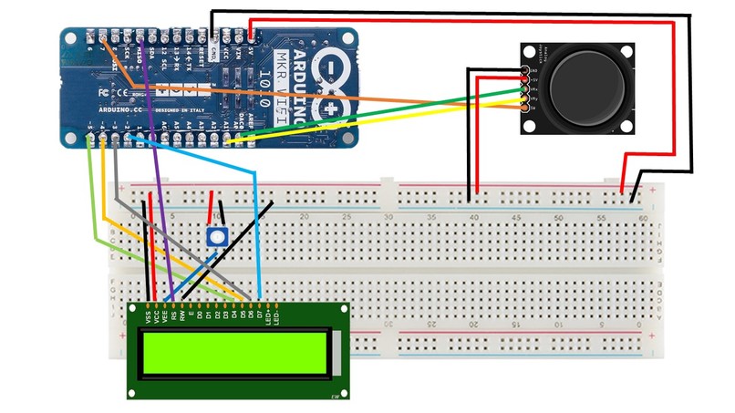
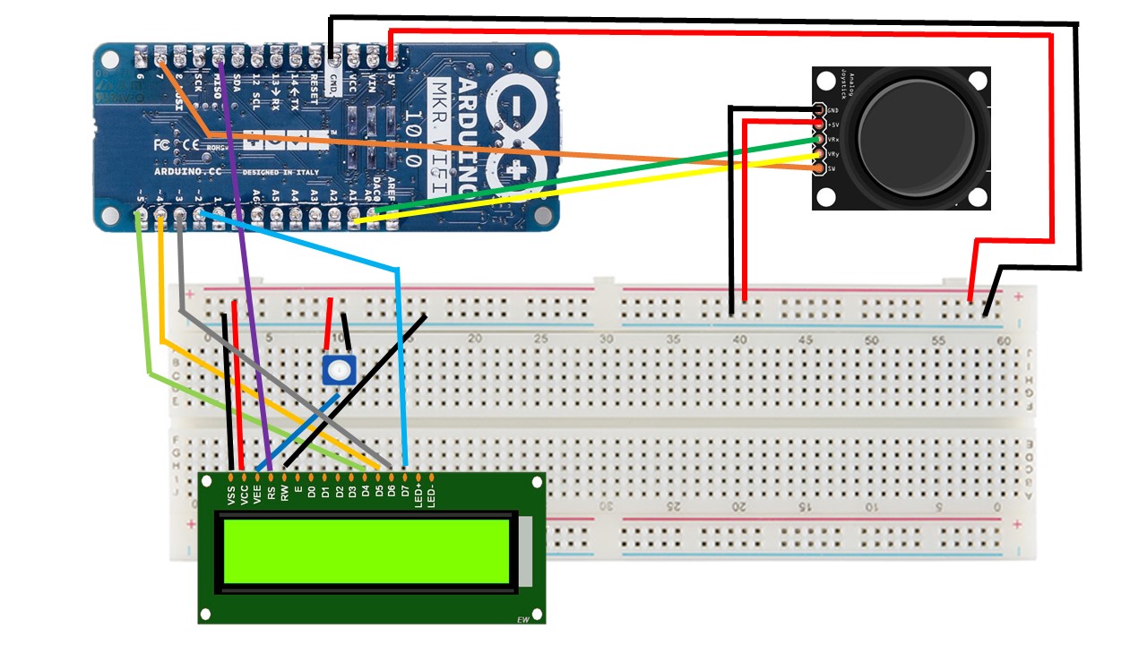
Circuit Diagram
-
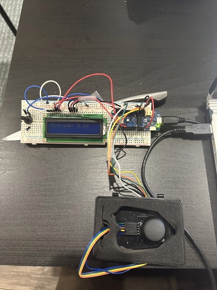
QuickFlick
-

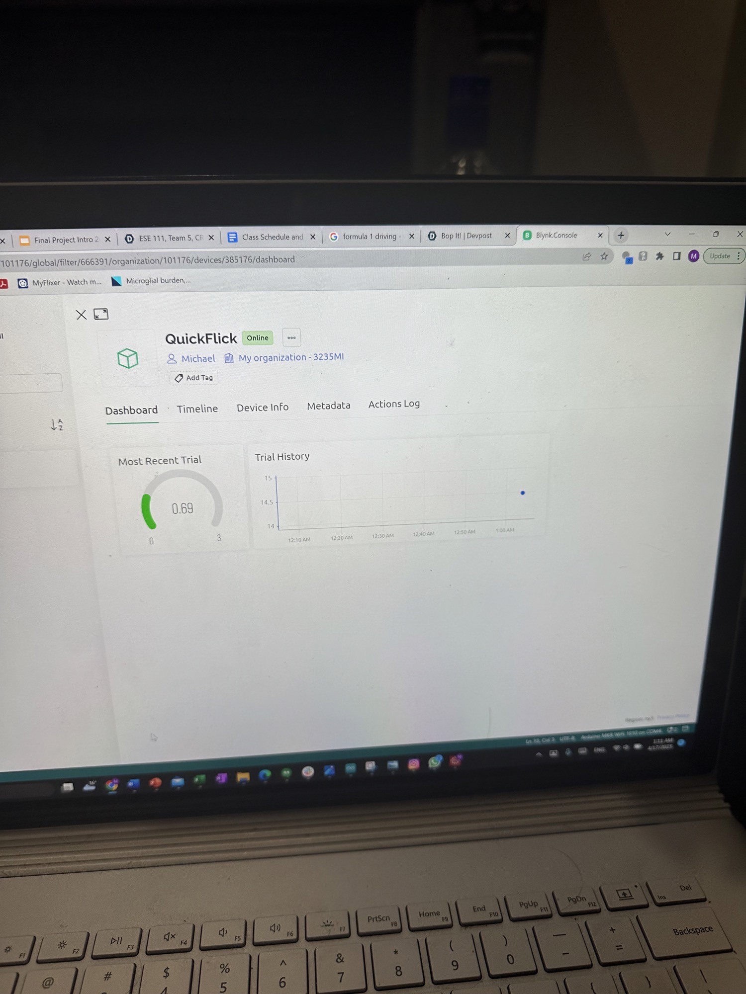
Track your progress!
-
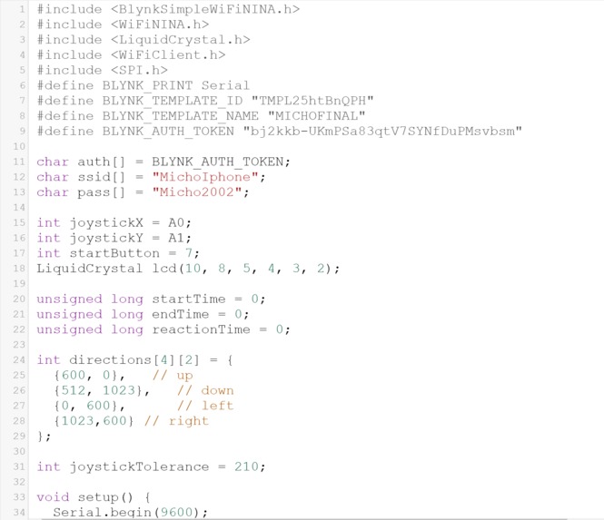
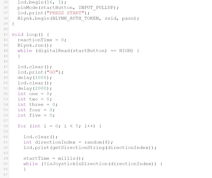
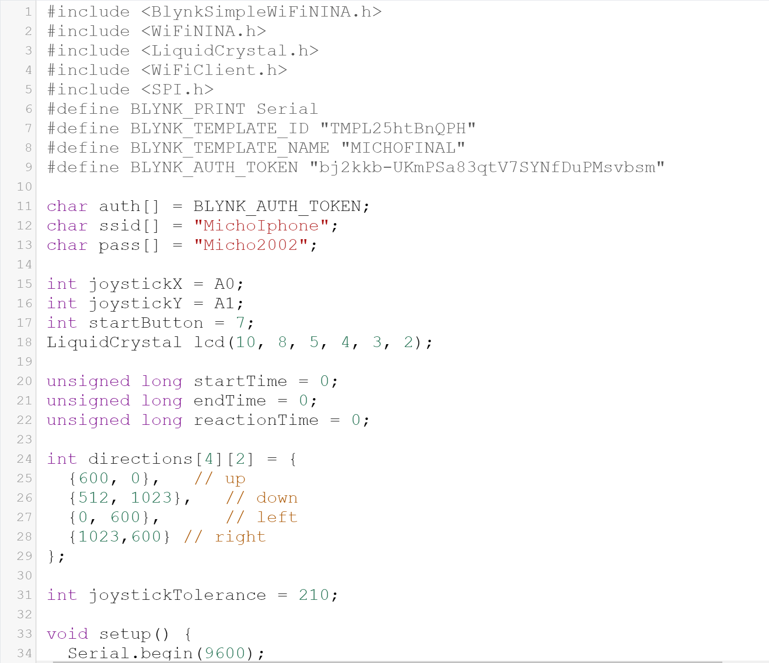
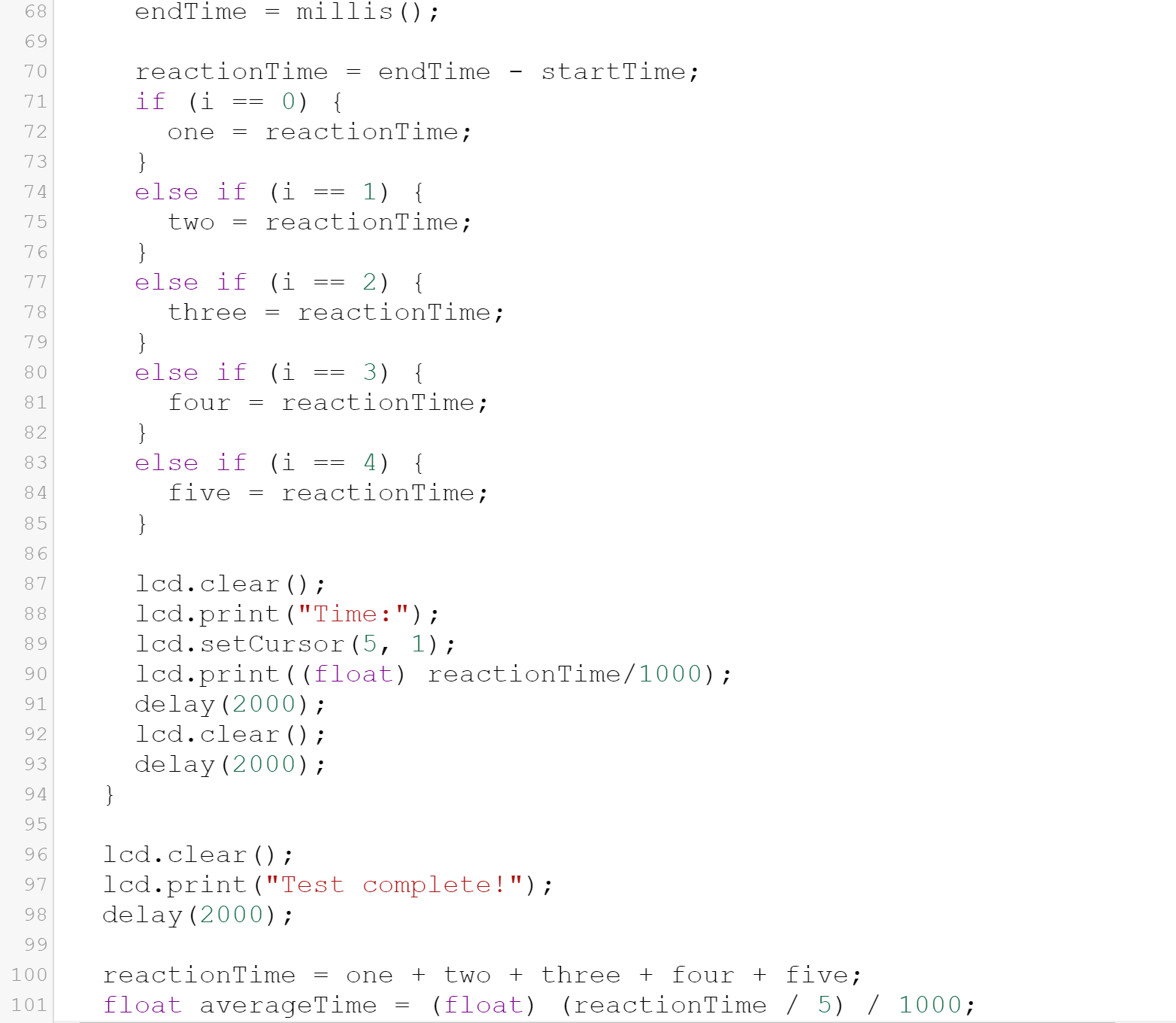
Code Snippet (1)
-
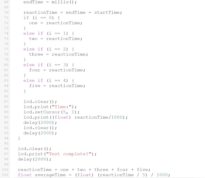
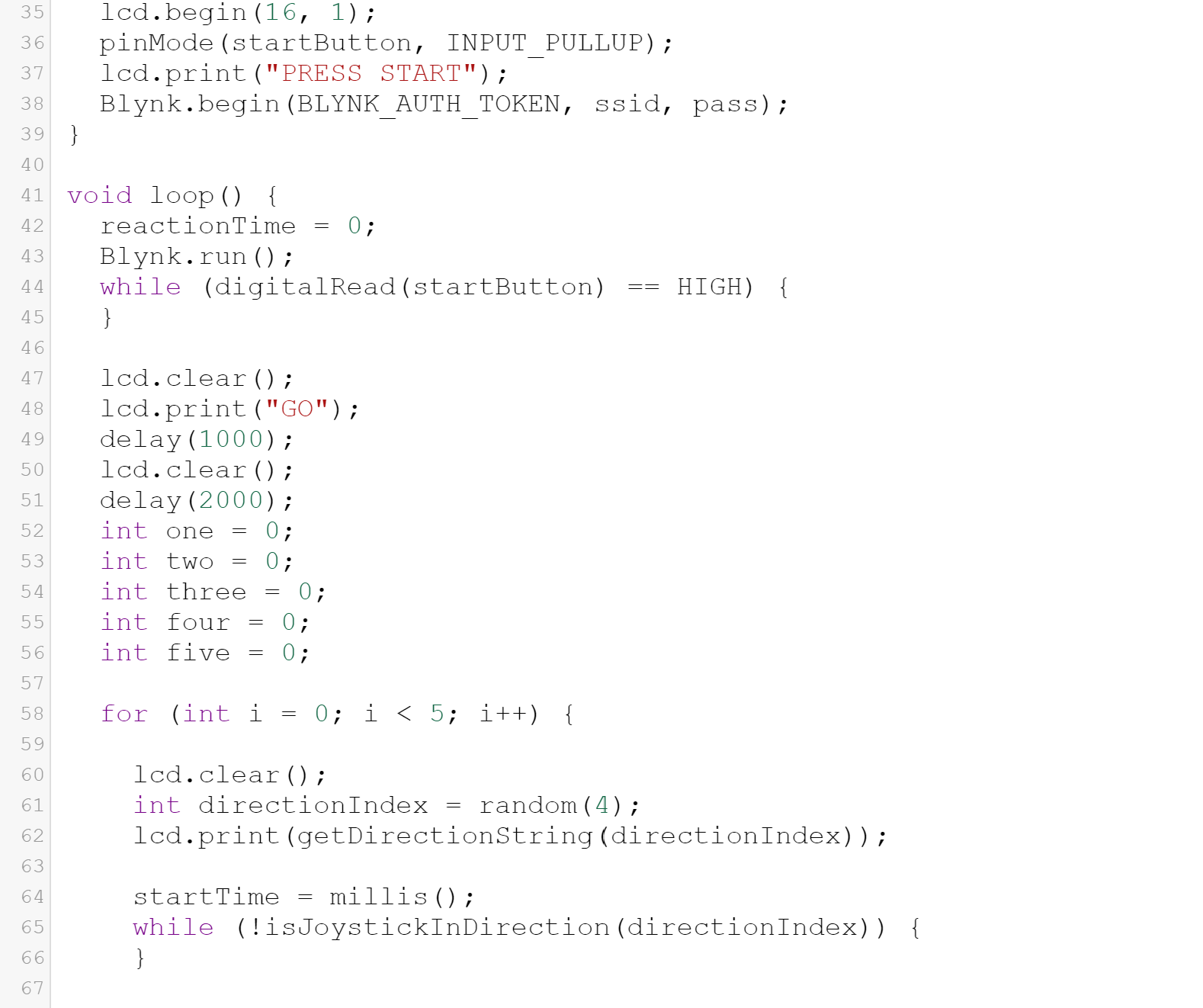
Code Snippet (2)
-
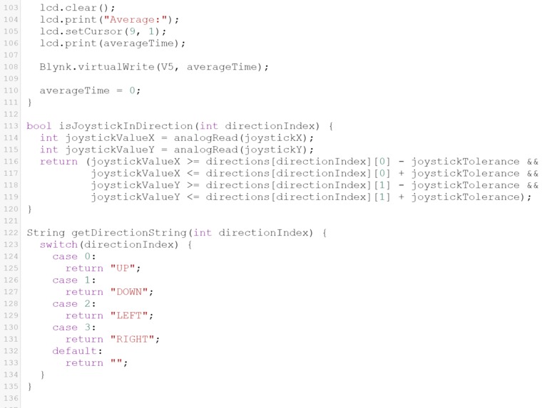
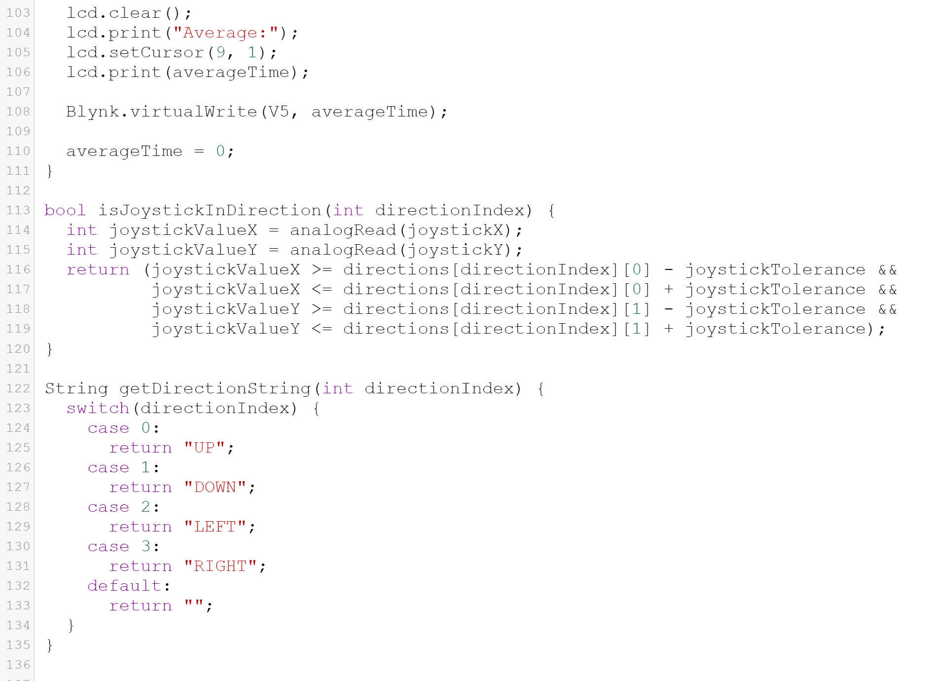
Code Snippet (3)
-
Code Snippet (4)

Inspiration
Improving reaction times is a vital goal in many athletic and academic professions, from Formula-1 racing and soccer goalkeeping to surgery and aviation. Having recently gotten my novice pilot license, I’ve witnessed firsthand the importance of being able to react quickly in different situations, and QuickFlick is the perfect way to keep my reaction-time as sharp as it can be.
What it does
QuickFlick is a portable reaction-time tester designed to improve your reflexes and cognitive performance! The user is shown one of four directions on an LCD screen (up, down, left, or right) and must reproduce the corresponding movement on a joystick as swiftly as possible. QuickFlick repeats this for 5 trials, then computes the average of these trials and sends the result via Blynk to the user’s laptop or phone, allowing them to track their progress and gradually improve their reaction time.
Electronic Components used
- MRX1010 (Arduino MKR Wifi 1010)
- 16x2 LCD screen
- Joystick
- Potentiometer (to adjust screen brightness)
- Jumper wires ## IOT Component
- Blynk
Design Process, Iterations, and Challenges Faced
I initially tried to build QuickFlick using the Arduino Uno Board (Rev3) and the Arduino Wifi Shield, where the average reaction time would be sent via Twilio to the user’s phone as a text-message. However, it turned out that the Wifi Shield drew too much power from the LCD, which no longer lit up, so I switched to MRX1010 which is an extremely easy point of entry to IOT. The challenge here was mapping the pins from Arduino, which I knew how to use, to MRX1010, which was especially tricky since there are fewer pins on MRX1010.
After setting up the circuit with MRX1010, I first aimed to get the joystick functioning properly, but found that the movements made on it would have to be very precise, which was quite uncomfortable (you would have to go exactly 90 degrees up to successfully make an “up” movement, for instance). To tackle this challenge, I created the ‘Joystick Tolerance’ variable, shown in my code snippets, to allow for tolerance in the joystick movement, so a user could perform a successful movement without having to move with absolute precision.
Another challenge I faced, since I did not have any coding experience before the class, was writing the code to perform 5 consecutive reaction-time-tests, and calculating the reaction time from each of these tests before computing the average. I’ve shown the code in my schematics, but it was tricky figuring out how to get it to calculate the 5 different results.
I also spent considerable amount of time getting the IOT component Blynk to work. I had first tried to use Twilio and ThingSpeak, but, despite working hard with the TA’s and Detkin Staff, I was not able to successfully get the TCP to connect with the remote host. I then switched to Blynk, which was also very tricky since I had to find the right libraries for MRX1010, but I was happy I was eventually able to make the successful connection with my phone hotspot.
Accomplishments I’m Proud of
Firstly, I am proud to have successfully learned how to use the Joystick module, because it was tricky to find the correct coordinates for the specific movement directions. I am also proud to have figured out the IOT component, especially since I was using MRX1010, which meant that I had to find new libraries and connect to different pins. Finally, I am most proud of the code I wrote. Before this class, I had no experience whatsoever, I did not even know what a loop was, and so I am extremely proud to have tackled the challenges I faced and made QuickFlick work.
What I learned
I learned how to use MRX1010, and the process of mapping pins from Arduino Uno to MRX1010. I also learned how to use the Arduino Joystick module, which I hope to use in future projects. I also learned how to write code on my own, which is what I am most proud of.
What’s Next for QuickFlick
The first aspect of QuickFlick we will be looking to improve is the difficulty of the task, which would enable QuickFlick to help improve cognitive performance in addition to reaction time. For instance, instead of displaying one single direction, we could have a sequence of directions (“up, left, right, right”) that would test the user’s focus in addition to their reaction time. Another hurdle we have not been able to overcome is the reaction time of the Arduino MRX1010 itself, which has led to inflated readings of the user’s reaction time. It would be extremely beneficial to figure out how to account for this reaction time, in order to convey more accurate data. However, it is worth mentioning that the exact numbers provided by QuickFlick are not as important as the trends in reaction time over different trials, which would tell a user whether they are improving or getting worse. We will also be looking to allow the user to select how many trials they would like to do, rather than set the hard number of 5 trials, which could enable users to practice for extended periods of time and maintain a high level of focus over longer intervals. Another future goal is to 3D-print a housing for the joystick in order to improve user experience, and make the handling of the joystick more comfortable.
Built With
- arduino
- mrx1010

Log in or sign up for Devpost to join the conversation.