-
-
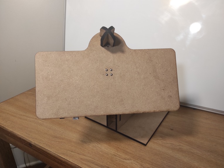
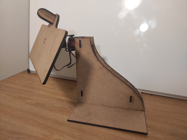
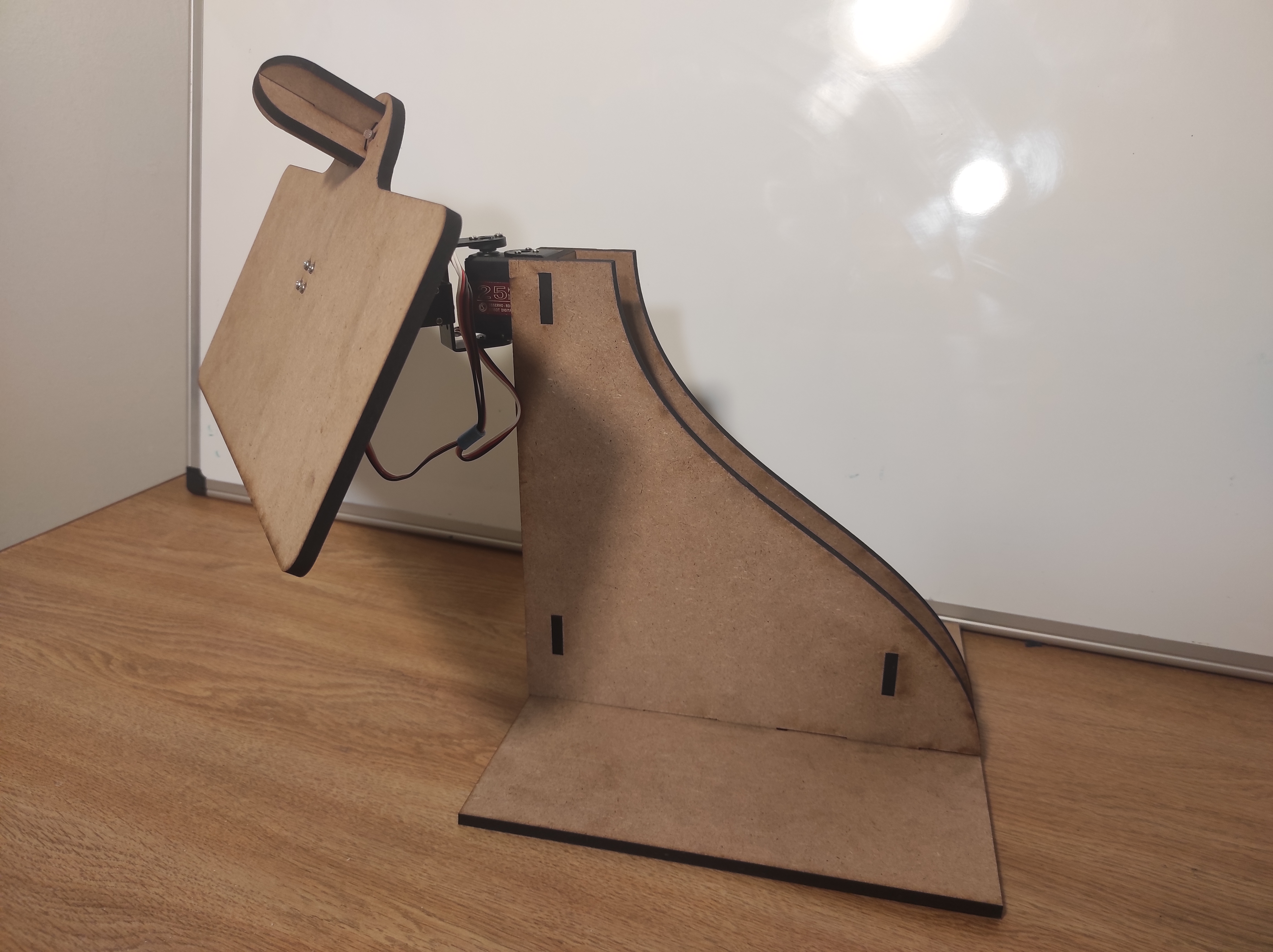
Front View
-
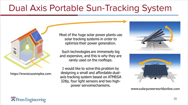
Dual Axis Sun-Tracking System
-

Main Idea
-
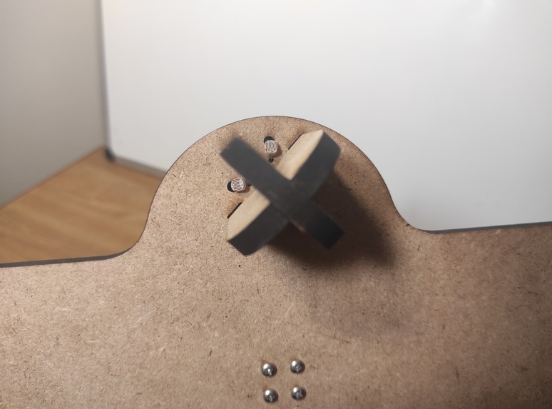
Solar Direction Sensor
-
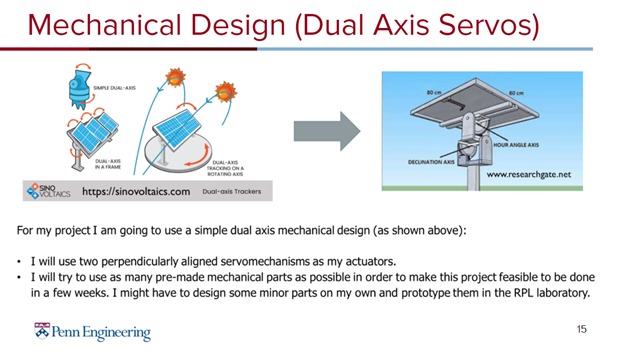
Mechanical Design
-
Mechanical Structure
-

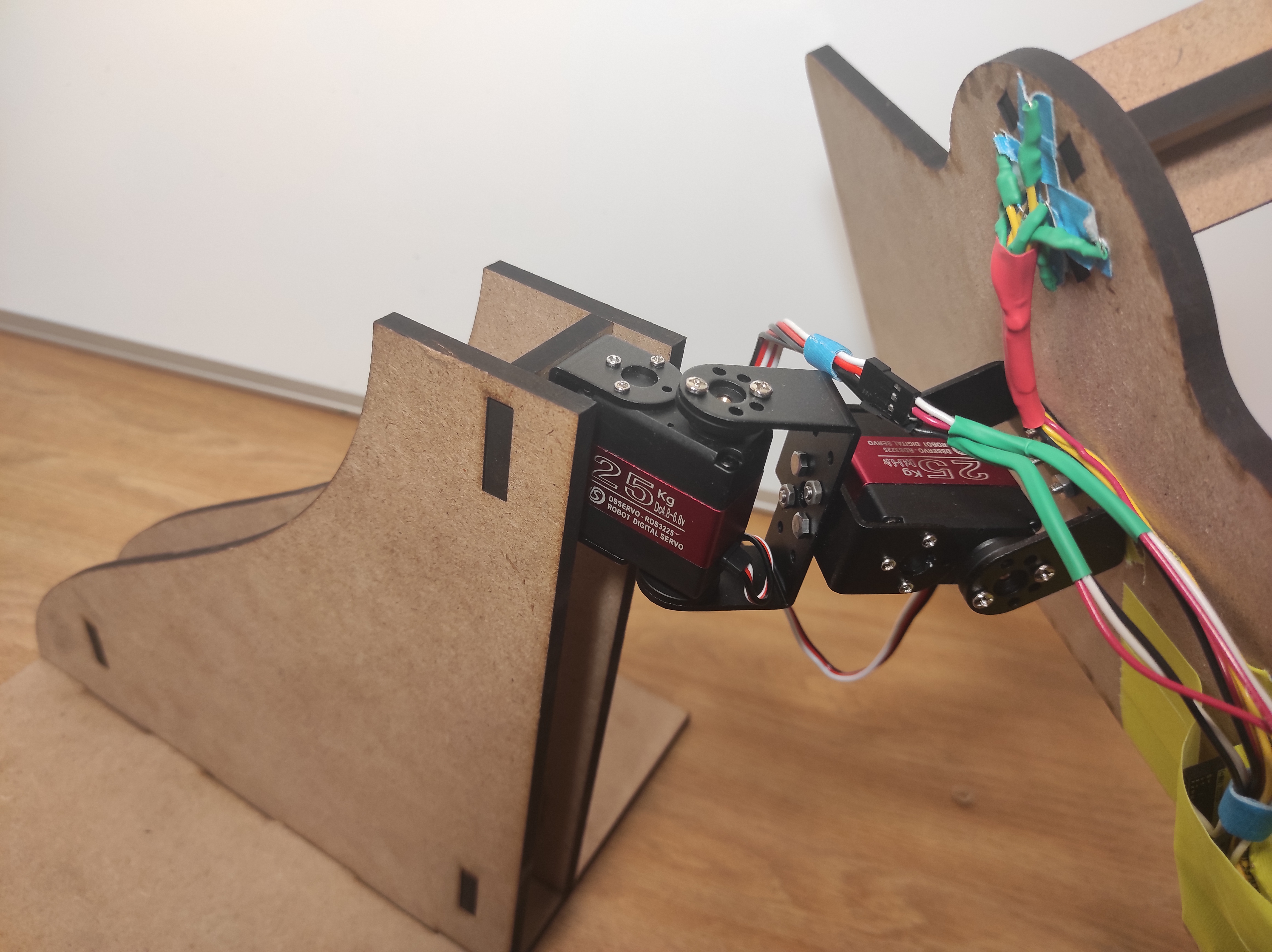
Servomechanisms
-
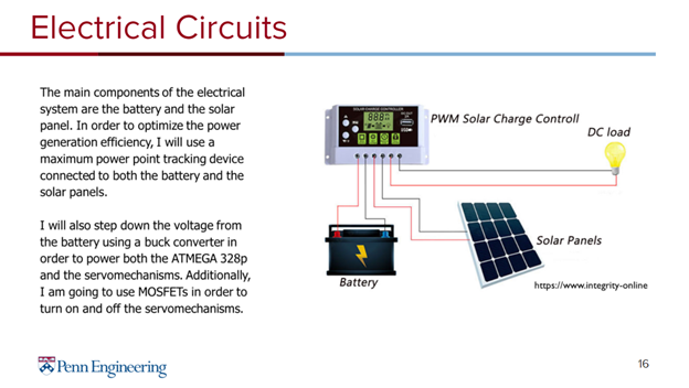
Electrical Circuits
-

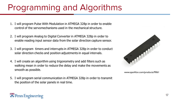
Programming and Algorithms


Abstract:
Solar tracking systems are commonly used around the world in order to optimize the power generation. Unfortunately, such technologies are usually too big and too expensive to be used in the commercial sector. I would like to use my final project to solve this problem. I am going to create a small and affordable dual axis solar tracking system that will follow the sunlight (align the solar cells perpendicularly to the sun rays). This project is going to involve a wide range of different topics that I have learned in the ESE350 so far. First, I am going to create the electrical system consisting of a battery, solar panels, maximum power point tracking device and some buck converters. This is going to ensure that my system will be self-sufficient (powered entirely from a renewable energy source). Next, I am going to create the mechanical structure for my system consisting of a solar panel, two servomechanisms and a self-made solar direction capture sensor. Finally, I am going to program the ATMEGA 328p microcontroller in order to control the two servomechanisms based on the data read from the solar direction sensor. Overall, I am going to aim to create a system that will significantly reduce the delay in tracking the sunlight and make the movements of the solar panels as smooth as possible.
Motivation:
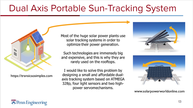
Most of the huge solar power plants use solar tracking systems in order to optimize their power generation. However, such technologies are immensely big and expensive, which renders them virtually useless in the commercial sector. I would like to solve this problem by designing a small and affordable dual-axis tracking system based on ATMEGA 328p, four light sensors and two high-power servomechanisms. This project is extremely interesting to me, because for the past two years I have been developing my own solar battery charger with a maximum power point tracking module. I always wanted to buy a solar tracking device in order to test my battery charger, however it was too expensive. Now, thanks to this class, I will be able to use my new knowledge in order to construct something very useful for my personal project. As mentioned above, the intended purpose of my final project is giving me a platform for determining the efficiency of my solar battery charger, and also introducing portable dual axis solar tracking systems into the commercial sector.
Goals:
- Creating the solar battery charger circuitry.
- Creating the low voltage system to power the ATMEGA and servomechanisms.
- Creating the mechanical structure supporting the solar panels.
- Creating the servomechanism system allowing for dual axis rotation.
- Creating a self-made solar direction capture sensor.
- Enabling control of the servomechanisms used in the mechanical structure.
- Enabling reading input sensor data from the solar direction capture sensor.
- Conducting solar direction checks and position adjustments in equal intervals.
- Reducing delay and making the movements as smooth as possible.
- Using UART and serial port to transmit the current position of the solar panels.
Milestone 1
By the first milestone I expect to accomplish the following goals:
- Creating the solar battery charger circuitry.
- Creating the low voltage system to power the ATMEGA and servomechanisms.
- Creating the mechanical structure supporting the solar panels.
- Creating the servomechanisms system allowing for dual axis rotation.
- Enabling control of the servomechanisms used in the mechanical structure.
Final Demo
By the final demonstration I expect to achieve the following goals:
- Creating a self-made solar direction capture sensor.
- Enabling reading input sensor data from the solar direction capture sensor.
- Conducting solar direction checks and position adjustments in equal intervals.
- Reducing delay and making the movements as smooth as possible.
- Using UART and serial port to transmit the current position of the solar panels.
Methodology:
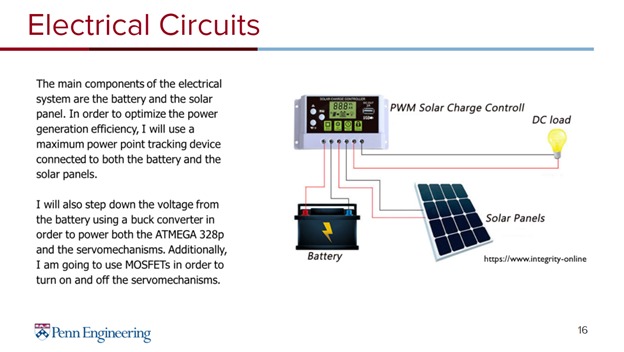
- Creating the solar battery charger circuitry: Two main components of this system are: battery and the solar panel. In order to optimize the power generation efficiency, I will have to use a maximum power point tracking device connected to both the battery and the solar panels.
- Creating the low voltage system to power the ATMEGA and servomechanisms: I will step down the voltage from the battery using a buck converter in order to power both the ATMEGA 328p and the servomechanisms. In addition, I am going to use MOSFETs in order to turn on and off the servomechanisms.
- Creating the mechanical structure supporting the solar panels: I will try to use as many pre-made parts bought online as possible in order to make this project feasible to be done in a few weeks. I might have to design some minor parts on my own and prototype them in the RPL laboratory.
- Creating the servomechanisms system allowing for dual axis rotation: Hopefully, I am going to find a pre-made dual servomechanism system available online. I am going to integrate it with my mechanical structure.
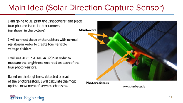
- Creating a self-made solar direction capture sensor: I am going to use a 3D printed case and place four photoresistors in its corners (please see the slides below). I will connect those photoresistors with normal resistors in order to create four variable voltage dividers.
- Enabling control of the servomechanisms used in the mechanical structure: I will program Pulse With Modulation in ATMEGA 328p
- Enabling reading input sensor data from the solar direction capture sensor: I will program Analog to Digital Converter in ATMEGA 328p
- Conducting solar direction checks and position adjustments in equal intervals: I will program timers and interrupts in ATMEGA 328p
- Reducing delay and making the movements as smooth as possible: I will create an algorithm using trigonometry and add filters such as walking mean.
- Using UART and serial port to transmit the current position of the solar panels: I will program serial communication in ATMEGA 328p.
Components:
- ATMEGA 328p: This microcontroller is going to be used in order to enable control of servomechanisms and read data from the solar direction sensors.
- Solar Panel: Solar panel is going to be used in order to charge the battery.
- Maximum Power Point Tracking device: MPPT will be used in order to increase the efficiency of the power conversion.
- Battery: Battery will be used in order to store energy generated by the solar panels and power the ATMEGA 328p / the servomechanisms.
- Pan/Tilt servomechanism kit: Dual axis servomechanisms are going to be used as the base for the mechanical structure supporting the solar panel.
- Four resistors and four photoresistors: Four resistors and photoresistors will be used to create four variable voltage divider networks that will detect the direction of the sunlight.
- MOSFETS: MOSFETS will be used to either enable or disable the servos.
- Buck converters:
- I will use buck converters in order to supply low voltage to both the ATMEGA328p and the servomechanisms.
Evaluation:
There are three main metrics for evaluating how well my product solves the problem:
- Efficiency metric: I am going to compare power generation efficiency of a static solar panel with the efficiency of the same solar panel with my solar tracking system. The higher the efficiency of my system compared to the static alternative the better.
- Delay metric: Lower response time of my tracking system for change in the direction of sunrays is going to indicate better performance.
- Smoothness metric: The movement of the solar panel should be as smooth as possible.
Results:
At the end I have managed to successfully achieve 9 out of 10 of my goals for the project:
- I have successfully implemented the low voltage system to power the ATMEGA and created the - mechanical structure that could be used to support solar panels.
- I constructed the servomechanism system allowing for dual axis rotation.
- I created a self-made solar direction capture sensor. I have also enabled the following software features (you can find my code on github):
- Enabling control of the servomechanisms used in the mechanical structure.
- Enabling reading input sensor data from the solar direction capture sensor.
- Conducting solar direction checks and position adjustments in equal intervals.
- Reducing delay and making the movements as smooth as possible.
- Using UART and serial port to transmit the current position of the solar panels.
Conclusion
Overall, I am very satisfied with the project. I believe that my device does a great job in most of the metrics that I have established for the purpose of its evaluation. The efficiency of power generation using my solar tracker is obviously much greater than the efficiency of a static system. Additionally, the device finds the correct position relatively quickly, which indicates a good performance. At some point during the development of this project, I have learned that “smooth” movements of my system are not desirable. This is because constant smooth movements of servomechanisms consume a lot of power. This power in the worst case scenario could possibly exceed the power loss that is being saved thanks to the solar tracking. This is why I decided that in my device servomechanisms should move in rather large discrete steps. In the future I would like to implement the entire system connected with real photovoltaic panels. In order to achieve that I would have to design an electrical system containing MPPT device, buck converter and a battery. After that I would like to perform comprehensive tests comparing the efficiency of power generation using my platform with some other dual-axis tracking alternatives.
Built With
- atmega328p
- c
- draftsight
- lasercutters
- microchipstudio
- photoresistors
- servomechanisms
- solidworks
- voltagedividers

Log in or sign up for Devpost to join the conversation.