-
-
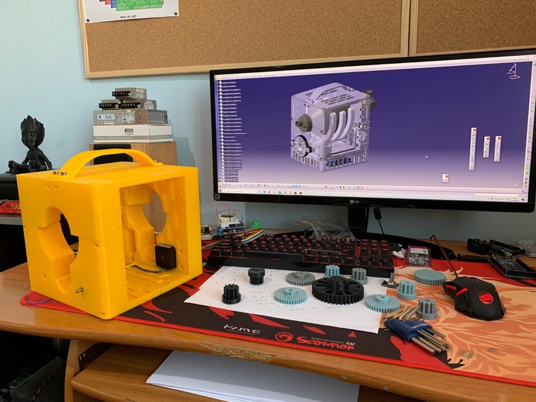
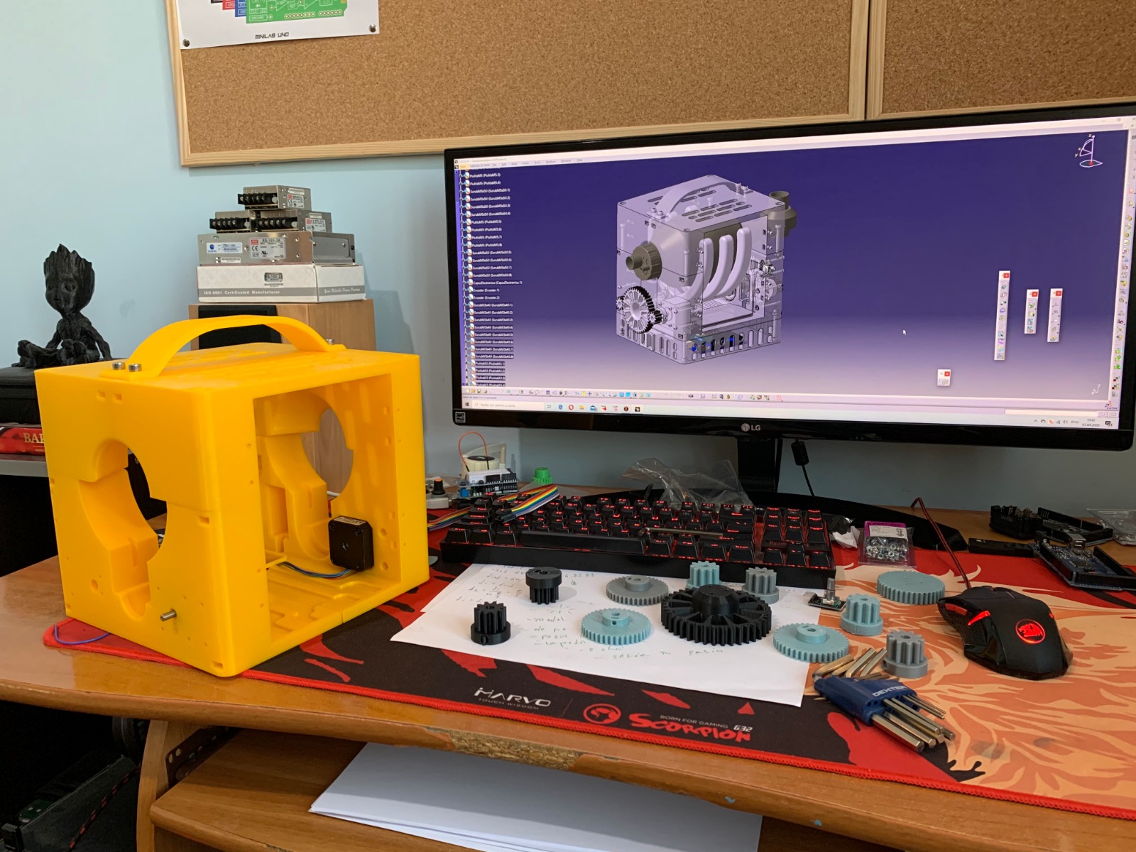
First version of PVM (CAD and partially built prototype)
-
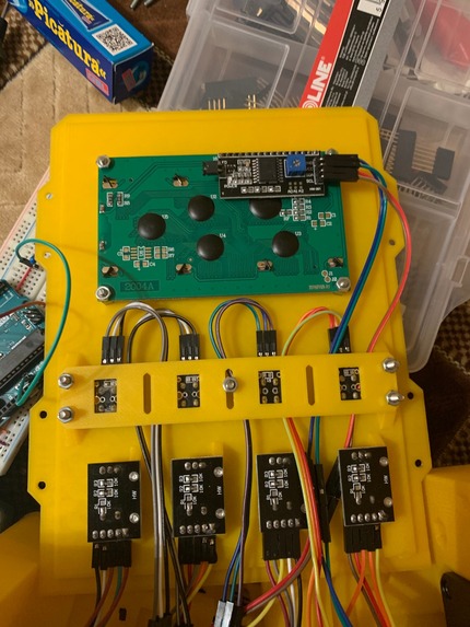
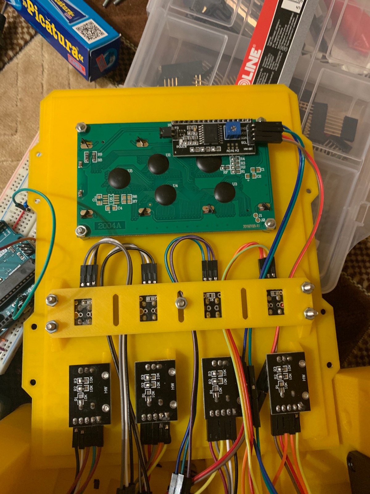
Cabling of the first version of PVM
-
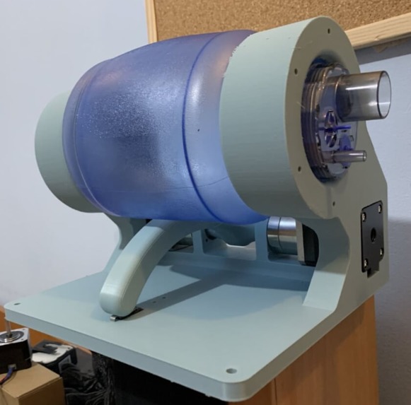
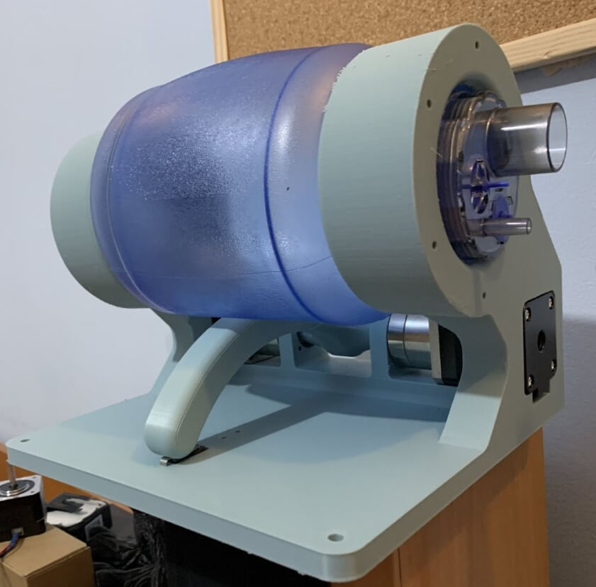
Testing stand with BVM
-
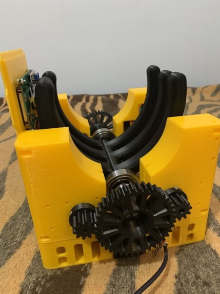
Mechanics
-
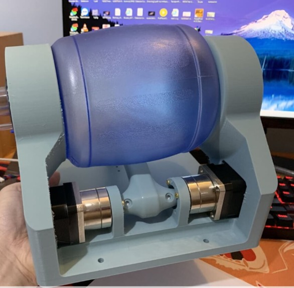
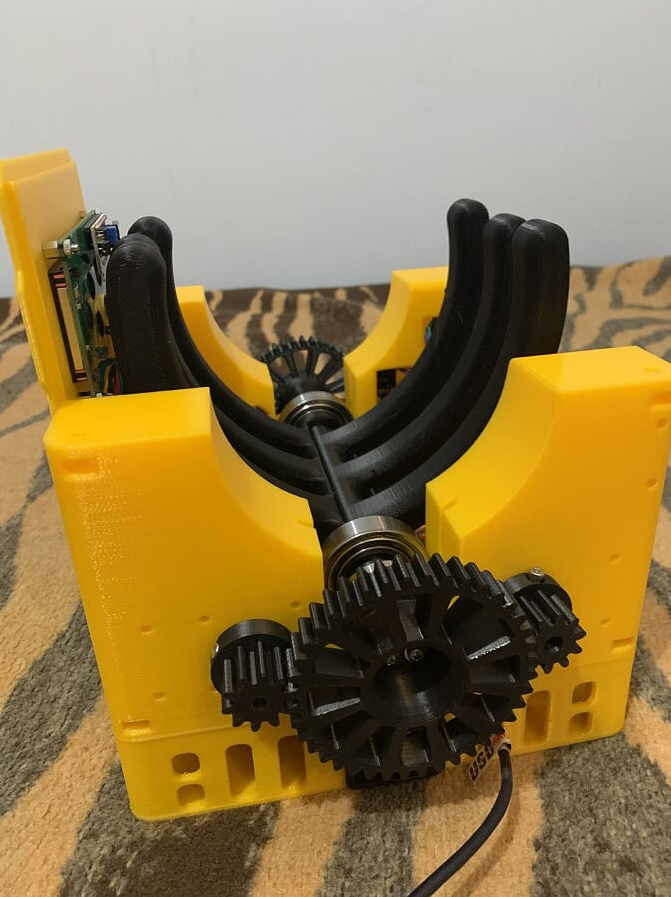
Testing stand for mechanics with BVM
-
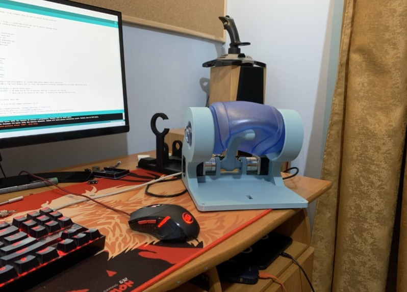
#2
-
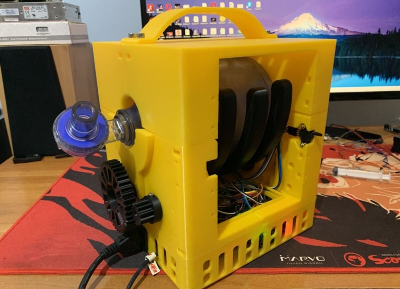
Functioning tests with BVM
-
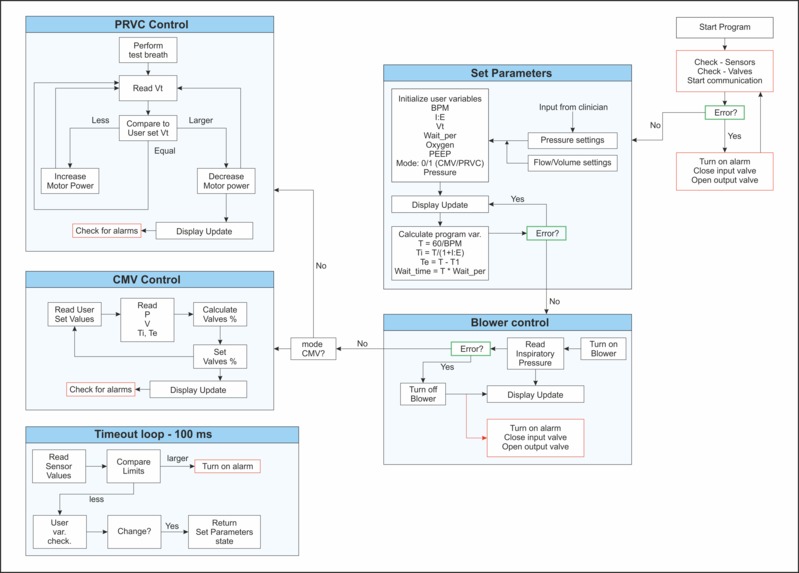
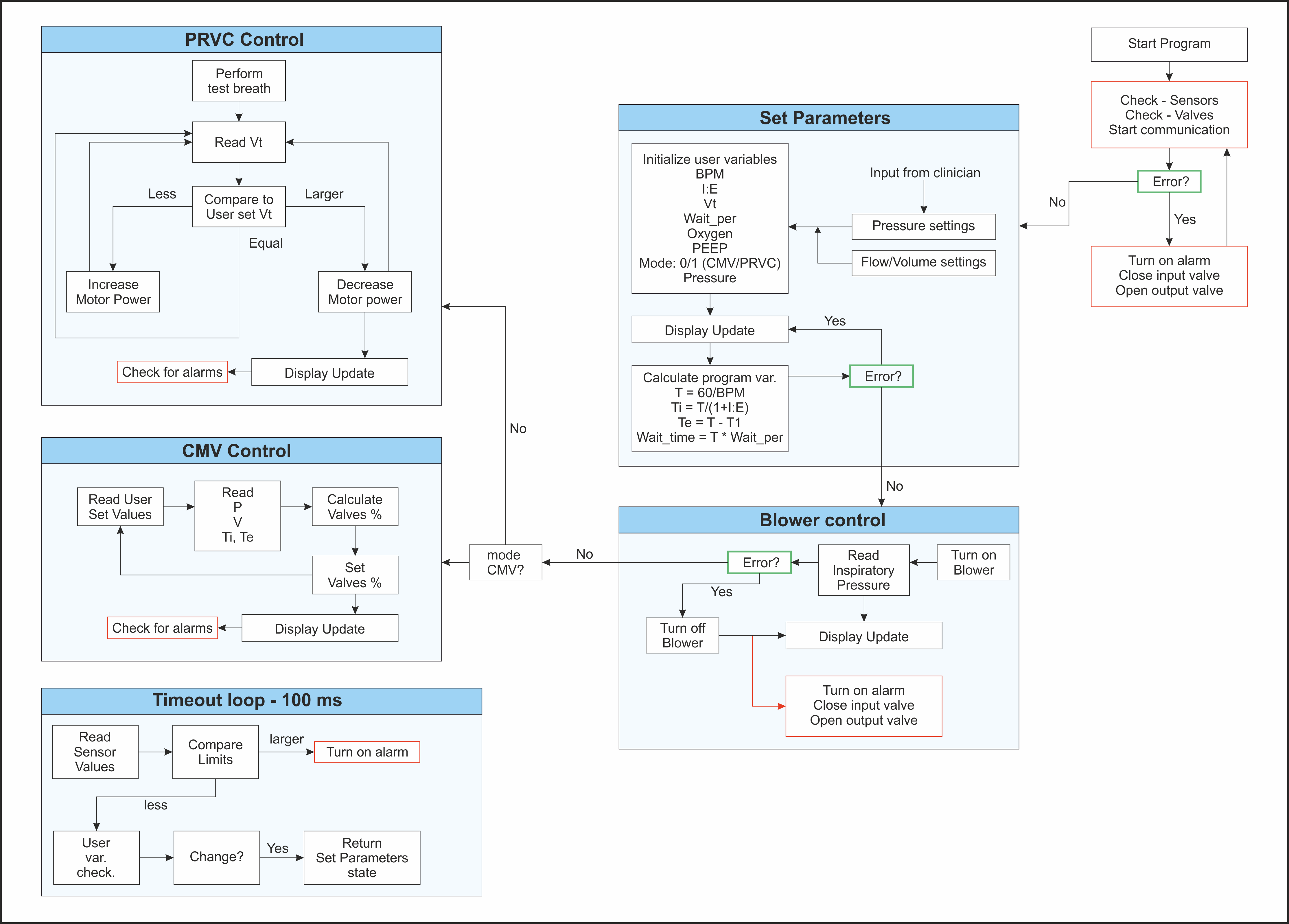
Control system block diagram for PVM system
Inspiration
Our main motivation comes from the current Medical Ventilator crisis and the way prices goes up and stocks are being empty. As a human being, one is bound by his consciousness to do whatever he can to help his fellow men and try to do his or her small part to restore the world to its proper order. As engineers of technological development, we humbly believe that we can provide some small contribution towards repairing this crisis. As such, we decided to try our part in hacking this problem.
What it does
As a precautionary measure we need a universal model for a medical ventilator that be safely used and be deployed on a massive scale such that it has the most impact. This ventilator must meet the minimum requirements to be useful, pressure regulated volume control mode with PEEP support. Also, it should be able to trigger on patient inspiration and expiration, either by pressure or flow triggering. This ventilator needs to be designed with only the most widely available components such that disruptions in the distribution chain does not impair its manufacturing and must be very simple to assemble. The end goal is to have a system consisting of two 3D printed parts, a brushless DC motor, microcontroller with 5 pressure sensors and 2 flow sensors, a simple user interface based on a 20x4 LCD with one rotary encoder and two push buttons as input and an oxygen supply line with an adjustable needle valve.
How I built it
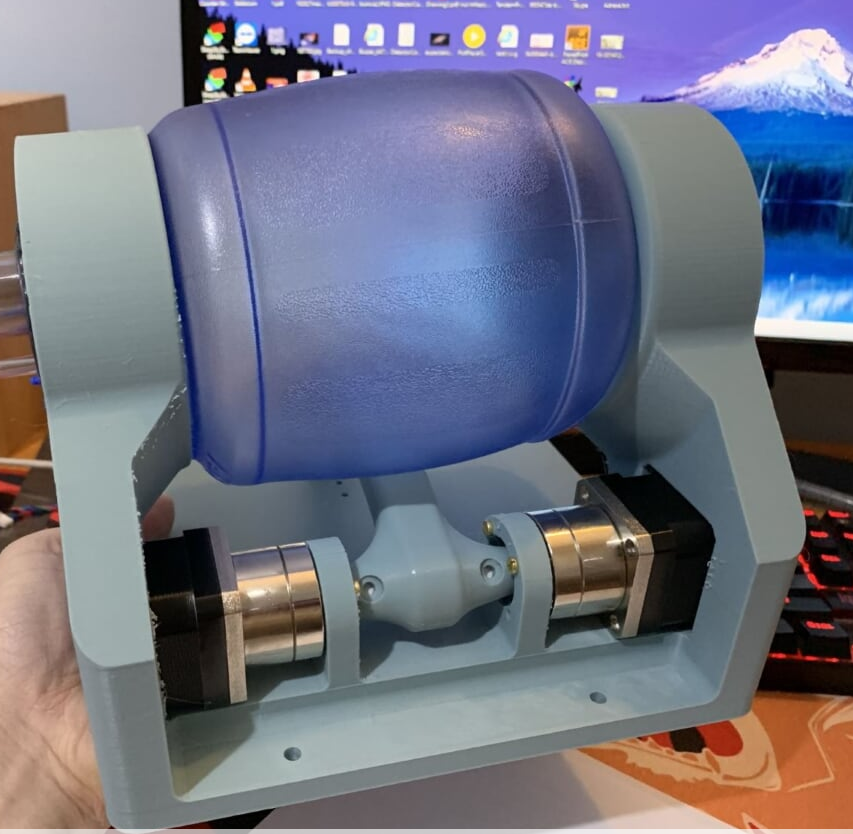
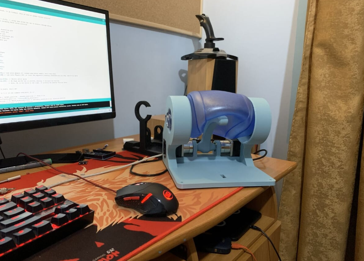
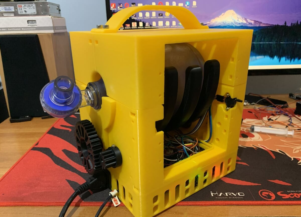
Like many other teams, we started with using an AmbuBag and designed different versions of mechanical actuators to compress the bag and software to control it. Unfortunately, this idea has some drawbacks, the main problem is that the AmbuBag balloon is not designed to be compressed repeatedly by mechanical means which leads to deteriorations. It is not suited to provide the flows required for a realistic ventilator application. However, one main disadvantage is that the AmbuBag itself is expensive by comparison with other solutions and can become an item of limited supply. A better approach is to replace the entire AmbuBag and the mechanical system that compresses it with an air blower. This approach has several major advantages, the blower has a brushless dc motor which is by design compact and is very responsive, eliminating the need for valves altogether. For example, when the breathing cycle begins, the blower speeds up and when target pressure is reached, a simple comparison algorithm can adjust the motor such that flow is provided at constant pressure. This responsiveness is extraordinarily important since controlling the supplied pressure very thoroughly is what avoids barotrauma. By using the AmbuBag, we required a complex mechanical actuating system involving multiple gears and bearings which are not only a point of failure but decreases responsiveness of the delivered pressure. The second major disadvantage is the size and the third is the overall increased number of components. A centrifugal air blower has only a 3D printed chassis which is itself part of the ventilator main part and the turbine which is attached directly on the body of a brushless out runner motor, a quite simple design altogether.
It is because of this reasons that we are now concentrating on designing and testing a centrifugal air blower which is 3d printed and works with a very widely available brushless motor, the A2212 and can be controlled very precisely using the Arduino Uno. This is the platform we most prefer, the singular reason being that it is the most widely available development board and it is open source. The other components required for this application are seven pressure sensors (two of which will be used to measure the flow with the help of printed venturi valves) and one valve with adjustable flow, which will be a compressed air valve controlled with a servo motor and connected within a 3d printed frame. Our design goal is to have a 3d printed master template into which all other components are introduced to make a system that is as compact and easy to assemble as possible. All 3d printed components are designed in such a way that will make them compatible with injection molding such that manufacturing on a large scale can be accelerated.
Challenges I ran into
Mostly our main challenges have been procurement of required components. This has introduced several delays in our prototyping effort.
Accomplishments that I'm proud of
We have completed two major design variants that uses an AmbuBag for air supply, and although this is not the approach we plan to take any further, we have gained valuable experience from doing them.
What I learned
We have learned that the best design will be a minimal design. This seems simple enough, but it’s actually the most complicated aspect we have come across yet. Our final design will be reached when there is absolutely nothing left to take away.
What's next for PMV - Printable Medical Ventilator
Next, we will try to design a single block for 3d printing that contains the centrifugal air blower, a pressure sensor and a flow sensor. This will allow us to test whether or whether not we are on the right approach.
The main goal of the PVM initiative developed by the X-line team is to design and manufacture a prototype of a ventilator which can be mass produced using simple and accessible manufacturing processes.
- Resources for the project:
a. Equipment
i. CNC machine ii. 3D printer iii. Mechanical and electrical tools
The resources currently available are the tools and the 3D printer. When CNC machining will be needed, there is an option to outsource the manufacturing.
b. Materials:
The complete bill of material is annexed to the present document.
c. Human resources:
i. CAD engineer ii. Mechanical engineer iii. Electronics and automation engineer iv. Software engineer v. IC specialist vi. Management and procurement
The present team members fulfil all the above positions. Most of the time their skills and expertise overlap, which is a big advantage for the current project, making the distribution of work and the communication of the team members much easier.
- Activities of the project:
a. CAD design of the mechanical system
The design we propose is built around a blower system, widely used for the present purpose. The design will follow the goals of the project, making everything easy to be done through additive manufacturing techniques and with the best optimization in consumption of materials. We estimate this activity to about 4 weeks.
b. Design of the electronics and control
Everything to be used in the present project should be commercially available and way to be purchased. We propose using off the shelf electronics, sensors and controllers in order to go with the price and implementation time to the minimum. We estimate this activity to about 5 weeks.
c. Software development for testing individual components
In order to test individual components or parts of the system one should develop the software for this purpose. The software developed in this stage will be integrated in the final logic of the system. This activity goes in parallel with other activities that are independent on it. This activity is estimated to be about 4 weeks.
d. Procurement of the parts and materials
The procurement of the parts should start in the day 0 of the project, due to long lead times for several components. We expect that this activity should span over 8 weeks and should go in parallel with other activities.
e. Manufacturing of the mechanical parts
As stated before, we will go towards 3D printing technology for most of the parts. The main activity of manufacturing will consist of 3D prototyping. We estimate 8 weeks for this activity.
f. Testing individual components and parts of the system
This activity consists of testing individual parts, like sensors, controllers, motors, control electronics etc. but also test parts of the full system in order to study the feedback loops and dependencies. We estimate this activity to 6 weeks that will go for a while in parallel with the manufacturing activity.
g. Software development for the complete system
This activity continues the activity in section c. and it should be the final integration of the written codes and final testing of the logic. This activity is estimated to last 8 weeks and it goes in parallel for some time with the assembly activity which is dependent on it.
h. Assembly of the system
The final assembly of the prototype will take place in this period of about 6 weeks and is the main activity prior to final testing.
i. Testing of the system
The final testing of the prototype is done in this activity. We estimate that we will need about 6 weeks to perform thorough testing of the system.
j. Management of the project
This activity spans on the entire length of the project 24 weeks.
Following the period of the project there are two important activities that will be carried out by the team: certification of the prototype and entering mass production.
- Risk assessment
Risk #1 Delay in procurement process (low risk)
Mitigation Before proposing the present design, we developed another type of ventilation system. This allowed us to procure many of the parts that are needed. In case one of the procurement processes are delayed, we can continue working on other activities with the parts that we already have.
Risk #2 Manufacturing failure (low risk)
Mitigation Considering that most of the system will be 3D printed, benefiting on this widely use technique, we have enough resources around in order to mitigate this risk.
Risk #3 Failure of a part during tests (medium risk)
Mitigation We will procure a higher number of parts from the beginning, but also similar products from different manufacturers.
Risk #4 Software malfunctioning (high risk)
Mitigation In our previous attempts to build such a system we encountered several such problems, this is why we planned a bigger period in time for this activity.
Risk #5 Test failure (high risk)
Mitigation This process will be a trial and error process. This is the reason we planned a bigger period of time for this activity.
- Estimated budget for building the prototype (excluding salaries)
The total cost of building the prototype is depicted in the bill of materials for this project which will be submitted on the platform.


Log in or sign up for Devpost to join the conversation.