-
-

3D Render of the custom PCB
-

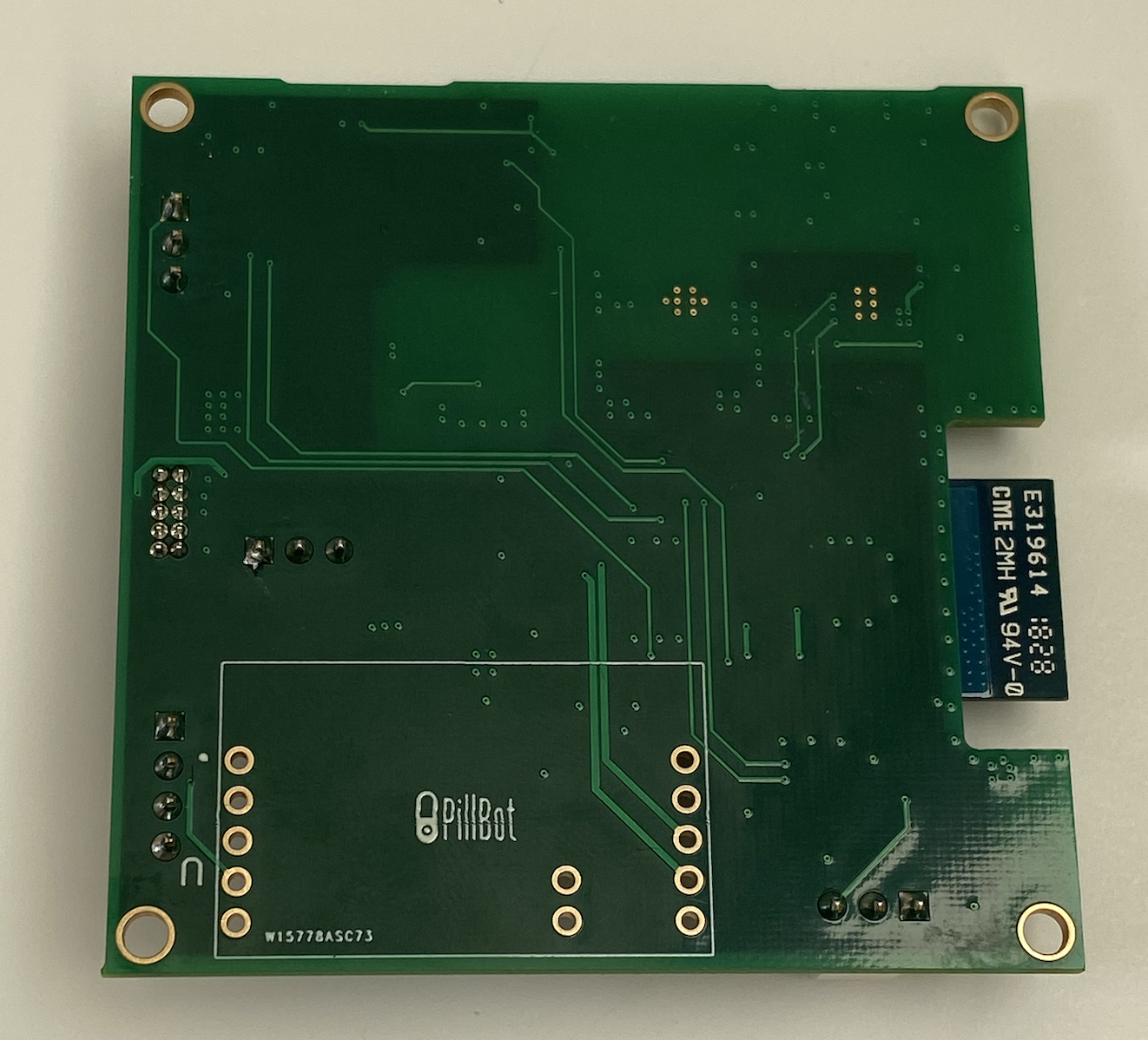
Photo of Actual Manufactured PCB
-
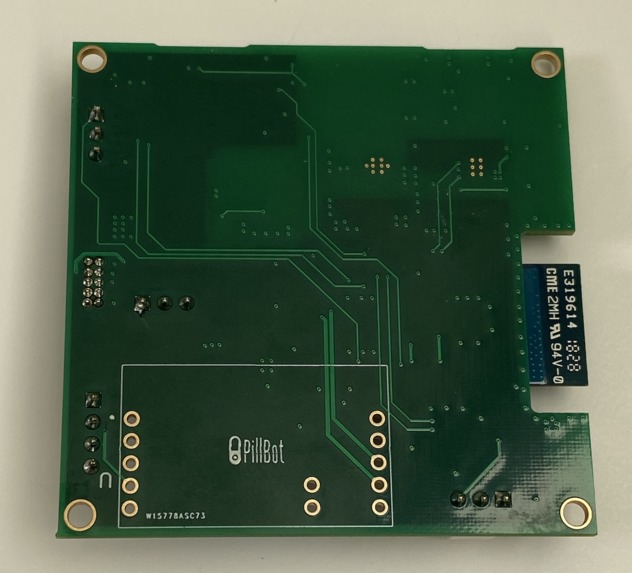
Back View of the PCB
-

Isometric View of PCB
-

PCB in Enclosure for Reference
-

Final Device Render (Closed)
-

Final Device Render (Open)
-

Protoype Device Lit Up
-

Top Down View of Device Assembly During Testing
-

Battery Management and Recharge Chip
-

Electronic Circuitry
-

Circuit with Charging and Power Optimization for Wake Up
-

Node Red Dashboard
-

Preliminary Decision Flow Chart
-

Node Red Back End
-

Preliminary Node Red Backend Continued


Meet the Team
Christopher Lee and Bryan Romanow are both juniors at Penn studying electrical engineering. Chris is part of the Jerome Fisher Management and Technology dual degree program, studying entrepreneurial management on the Wharton side. Bryan, on the other hand, is submatriculating into the electrical engineering Master's program.
Chris has experience in the medical device field and web development through his past ventures in start-ups and internships. Bryan has experience in PCB and mechanical design through his classes, clubs, and internships. Both members have a passion for tinkering and embedded development. Together, we make up the Pillbot team!
Inspiration
Despite coming from opposite ends of the country, both of us have seen close friends and family suffer from addiction to medication like opioids, with the only thing stopping patients being the simple lid on a standard pill bottle. As a result, the idea for PillBot was born. PillBot seeks prevents addiction before it happens by delegating to patients which medications to take and when. Not only does this help those with controlled substances, but PillBot can also help those with a typical pill regimen of up to 4 medications at a time by ensuring that someone does not miss a dose via notifications and non-invasive adherence tracking.
What it does
To accomplish its primary function, PillBot uses a variety of sensors and indicators to alert patients of which medications to take and when in addition to recording whether or not the patient performed an action to actually take their prescription, to ensure that they do not miss a dose.
How we built it
To accomplish our final goal of a "smart" pill organizer, we designed the entire PillBot device from the ground up in the form of a custom electrical PCB, 3D printed enclosure, and web user interface.
To create the PCB, the electronic CAD tool Altium was used to design schematics and board layout before having the assembly completed overseas. Online reference tools such as TI Webench and Atmel board planning for the device's power supply and MCU signals respectively. Several different sensors were integrated onto the PCB too. To signal to users which pills to take and when, a Neopixel LED matrix that communicated over I2C was used, using the SCL and SDA lines from the MCU and 5V from the onboard boost converter. Second, to track whether or not the lid of the device was opened, and thus a pill was extracted, a hall effect sensor was connected to the board with an accompanying magnet in the physical device which also communicated over the same I2C lines, except this time with power from the 3.3V buck converter. Lastly, to track how many pills remained in the device, a load cell and amplifier were utilized with its own data and clock lines with the boost as a power source. To ease debugging and ensure the best chance of the board functioning properly. PCB design best practices were used such as the implementation of bypass caps and diodes for filtering and protection, jumper resistors to isolate sub circuits if need be, fiducials for board assembly, and the constant reference of part-specific layouts for devices like the MCU/Wifi module and switching power supplies. Additionally, to allow our board to have some amount of modification post assembly, we ensured to attach headers for power, ground, and all data lines (proving to be quite useful later on). External from the PCB, we decided to add a battery recharge circuit to the device. While this was added extremely late in development, we believe that this is a logical next step to be fully integrated with the device as while our initial vision was for a countertop stationary device, a simple battery and recharge chip addition would make the device portable. Additionally, through some research and work in other embedded classes this semester, we learned of and decided to adopt here a simple on-off circuit which in theory would limit device power consumption when operating in battery-only mode.
For the 3D enclosure for the final device prototype, a mixture of 3D modeling software was used in the form of Rhino, Solidworks, and Ultimaker Cura. To design the enclosure, a 3D step of the finalized PCB was exported, and an enclosure was designed around it, ensuring to leave room for wiring and additional circuitry. A four-slotted divider main section with deep columns was ultimately iterated and decided upon as it intuitively lined up well with the signaling of the Neopixel array, and gave potential users ample room to store a full 30 day supply of most standard pills types. Lastly, the lid was designed with a simple hinge attachment mechanism and a transparent design to both conceal pills from view when the lid was closed, giving users a sense of privacy, but also allowing for the light of the Neopixel to be seen when the lid was open or closed so that users could see their prescribed dosages in either position.
For the NodeRed (JavaScript) integration, we leveraged the WiFi connection to the internet to reach the MQTT Broker.
A number of unique topics were targeted for both sending (publish) and receiving (subscribe) information to the MCU. Credentials to the broker as well as the definitions of these key topics can be found in the Wifi.h header file.
This Pub/Sub model enables secure communications, command, and control of our device from anywhere in the world.
Attached in the images of this DevPost is the flowchart explaining the entire layout of how M-Pill communicates with Node Red/the cloud. Since M-Pill relies on the cloud in lieu of a mobile app, it will have PII / HIPAA sensitive data concerns for the data items below that it needs to send to the cloud in a ‘Device-Twins’ fashion. (ie although the data is also local to the device, we’ll mirror status/info up in the cloud for easier debug / interaction.)
The below data endpoints are directly communicated to the cloud:
- User_ID
- Nbr_Pill_Types (ie Nbr of different compartments that are setup)
- Current_Nbr_Pills_Per_Type in container
- Dosage_Schedule_by_Pill_Type (twice daily, once a day, once per meal,etc..)
- Event_History (how ‘compliant’ is the End_User per Pill_Type)
Specifically, the datapoints used are as follows:
- User_ID, u_int32
- Nbr_Pill_Types, u_int8
- Array of PillNames[Nbr_Pill_Types], String
- Array of PillCount[Nbr_Pill_Types], u_int8
- Array of PillDose[Nbr_Pill_Types], pill_struct
- pill_struct
- Pill_Name, String
- Pill_Count, uint8
- Pill_Dose, dose_struct
- dose_struct
- days_of_week, String (S=Sun,M=Mon,T=Tue,W=Wed,H=tHu,F=Fri,A=sAt)
- Nbr_Pills, uint8 (How many pills to take per dose)
- HH1,uint8 // 1st dose Hour of day (up to 4 times/day supported)
- HH2,uint8 // 2nd dose Hour of day (Dose alerts to nearest hour)
- HH3,uint8 // 3rd dose Hour of day
- HH4,uint8 // 4th dose Hour of day So for example: 1 pill everyday at 9AM would be: {"SMTWHFA",1,9,0,0,0},
Specifically, information sent for each of the endpoints to node-red is as follows:
- User_ID: Generated UUID by incrementing Cloud User Counter, Subscribed by “M-Pill_Setup”
- Nbr_Pill_Types, Generated by User Input in Cloud, Subscribed by “M-Pill_Setup”
- Array_of_Pills, Generated by User Input in Cloud,
- Updates Published by “M-Pill_Setup”
- Subscribed by “M-Pill_Setup” after setup
To update the software on the board to sync with a patient's schedule, we leverage the working Wifi bootloader. In this current version of the system, it only works to download a file from a single website, but and does require a more involved framework for handling a full scheduling and data entry for multiple pill types, but it serves as a basis to be branched off of. Additionally, controlling the scheduling of the device in this manner rather than through the node-red portal means that even if the board loses Wifi connectivity, it will keep the same schedule and be able to behave properly in a standalone capacity. Also, one other design change that we made at the end was our method of sensing dosage taking. While we had originally decided to use the hall effect sensor to determine whether or not a pill was taken, we ultimately decided to alter this as a simple opening of the lid did not necessarily correspond to taking the pill (We still did develop the necessary drivers and add these libraries to the project though for reference). Rather, we decided to utilize a manual button press on the Neopixel array as a way of user interaction to ensure that they engaged with the device and thus most likely took their pill.
Lastly, the overall design process for this project was through a series of iterations and individual segments which ultimately had to be integrated to form a final project. Such an approach allowed for individual functions to be developed in an environment with known behavior and allowed for the verification of these features before combing them in the end. Additionally, due to time constraints on receiving the custom PCB, the entire circuit was initially built and tested on the starter Xplained board.
Challenges we ran into
During the design and implementation of our device, we ran into several roadblocks with a variety of solutions and final outcomes.
Our first hurdle to overcome was the routing and setup of our power supplies. Initially, in our schematic design, we had a flipped buck and boost setup where the ordering was swapped, and thus power would not be generated properly for the board. However, this was discovered post routing of the initial design. As a result, we gained some valuable experience in detecting such issues as well as correcting them while still trying to avoid a complete re-route. Overall, we were able to properly fix the layout and routing with relatively small alterations due to the localization of the chips' components and specified designs from their datasheets.
During the actual development of our final MVP, we had several issues with sensors. While we were able to get our libraries functioning for the LEDs, Hall Effect, and Load Cell Amplifier, we observed some non-ideal behaviors that caused us to pivot. First, our initial design for the board was to utilize another Neopixel strip of LEDs. However, upon actually working with the device and our desired form factor, it became apparent quite quickly that the Neopixel matrix would fit our design much better. Fortunately, this changeover was quite simple due to our exposed I2C, 5V, and GND headers. Second, four our load cell and amplifier, while we also did successfully implement this device, the reads that we obtained for the device were non-ideal. That is, we had envisioned recording the mass of small numbers of pills being removed from each container. However, the load cell that we ultimately purchased was still not sensitive enough for this purpose and only detected consistent readings in far excess of what we had intended. Due to the limited time frame, we were unable to purchase and test a new load cell, but in theory, this change should be quite simple as the interface with the load cell amplifier stays constant. Lastly, we had integrated our hall effect sensor onboard using I2C and 3V power. However, upon actually trying to use it in the device, it became quickly apparent that this placement was not ideal. However, since we had obtained a separate breakout board with an identical hall effect sensor attached, we were able to attach this additional device to the aforementioned headers and place it closer to the magnet in the device. On this note, we also had to switch to much larger, stronger magnets as those we had originally chosen yielded negligible changes in value on the sensor. Also quite, fortunately, this device has a simple one-component way of determining its I2C address, by the presence, or lack thereof, of a single resistor.
Accomplishments that we're proud of
Our number one accomplishment as a group would likely be the use of the hardware abstraction layer to generate working libraries for our Neopixel, Load Cell Amplifier, and Hall Effect Sensor. Moreover, actually being able to control and upload from the board using the node-red platform using these libraries with a great moment for us. Last but not least, we were really excited when we had our first successful bootload over Wifi as this segment gave us a lot of trouble debugging across what felt like every step of the process.
What we learned
Through the course of the semester, we learned a significant amount about embedded development as a whole. While as a group, we had some knowledge of PCB design coming in, we certainly became far more proficient in areas such as filtering and protection circuitry in addition to high-speed data lines. Next, online software cloud programs like node-red and the use of MQTT were completely new to us and thus provided us with a good opportunity to learn more about these systems and how to use them, or similar platforms, in the future. Also, learning about how to leverage the hardware abstraction layer to convert libraries (or generate them from scratch) for sensors and other pieces of software designed for other MCUs was quite interesting to both of us as we had previously only been exposed to MCU specific handling. Lastly, we really found the lecture on device security to be quite relevant as we are planning on continuing this project, or a similar concept, in senior design next year in which case all of the skills we learned here are quite useful.
What's next for Pillbot
Moving forward, there are several key things that we want to pursue. First, due to the sensitive nature of the data being used with the device (patient medical prescriptions), we would want to research a more secure method of data transfer than the public MQTT broker used for this MVP. Additionally, on a security note, we would also want to pursue some kind of hardware and WiFi connectivity protection to ensure that devices could not be tampered with.
However, the most important next step for Pillbot would be to secure a feasibility study with a physician and actual patients to test whether or not the device can actually make a positive difference in the patient's pill-taking workflow. This would provide us with invaluable data in terms of device reliability, usability, and areas of improvement such as 3D design, UI, and complexity.
Some specific areas of interest for perfecting the design would be further work on a web UI for customizing and syncing schedules, full implementation of the battery and recharge circuitry as well as actual integration onto the PCB, and a change in actual load cell for more sensitive readings.
Built With
- altium
- atmel
- c
- c++
- hal
- javascript
- node-red


Log in or sign up for Devpost to join the conversation.