

Introduction
PicSoul is a light art installation consisting of a grid of wooden tiles with a mounted LED strip shining down on them from above. Each individual tile will act as a pixel by reflecting the light from the LED via a moving "arm" of servos positioned to tilt each tile; tilting up and facing the light source would be seen as “white”, tilting down and being completely shaded would be seen as “black”, and tilting in-between would be considered "grey". A camera installed in the front of the setup would captures images of passerbys as they glance at the installation; if they are smiling, then the tiles display a smiley-face, otherwise, the tiles display a frowny-face.
Baseline Goals (Revised)
Create a 2x2 grid of tiles where each tile attached to a servo. This initial goal serves as a proof of concept given that this is a relatively novel idea.
Find a sustainable method of being able to control the servos. Because we will be manipulating hundreds of tiles, attaching a servo to each tile is not a sustainable strategy (although this was our initial strategy, we quickly discovered its flaws). The two main methods we experimented were using electromagnets to control each tile and using a moveable "arm" of linear actuators composed of 9g servos. It was imperative that we demonstrate at least three different color gradients (i.e. white, grey, and black).
Scale the above design into a grid of at least 16x16 tiles and be able to display basic images (e.g. a rectangle) and at least three color gradients.
Reach Goals (Revised)
Integrate the camera and image processing software to be able to recognize whether or not passerbys are smiling.
Be able to automatically reset the grid of tiles back to a default position.
MVP
One Servo per Tile (Idea #1)
The very first step was to create a MVP proving that we could tilt laser cut wooden tiles to produce at least three different gradients of light. Is MDF a good material to use? Will the shadows cast by the tiles interfere with one-another? Is the idea even feasible to begin with?

Fortunately, after just two days in the lab, we successfully created a 2x2 grid that verified our initial idea. However, how will we get 400 servos and stay within budget? Short answer: we won't. Now that we successfully validated the idea, it was time to test idea #2.
Electromagnets (Idea #2)
After spending five days researching and testing different electromagnets and trying to figure out the best way to build/control them using a raspberry pi, we decided that the best way would be to create a series of electromagnets with a neodymium core and square magnet wire. We would then use a PWM controller to oscillate the current flowing through each electromagnet in order to finely control the tilt of each tile.

While this method is over 50% cheaper than using a servo to control each tile (~$1.00 vs $1.75), it was still too expensive to use at the scale we originally planned in our proposal. A 16x16 tile grid, the absolute smallest grid size we could reasonably display distinct images, would still cost ~$400 in raw materials for the electromagnets alone (not including power management). Unfortunately, this meant we had to move onto idea #3.
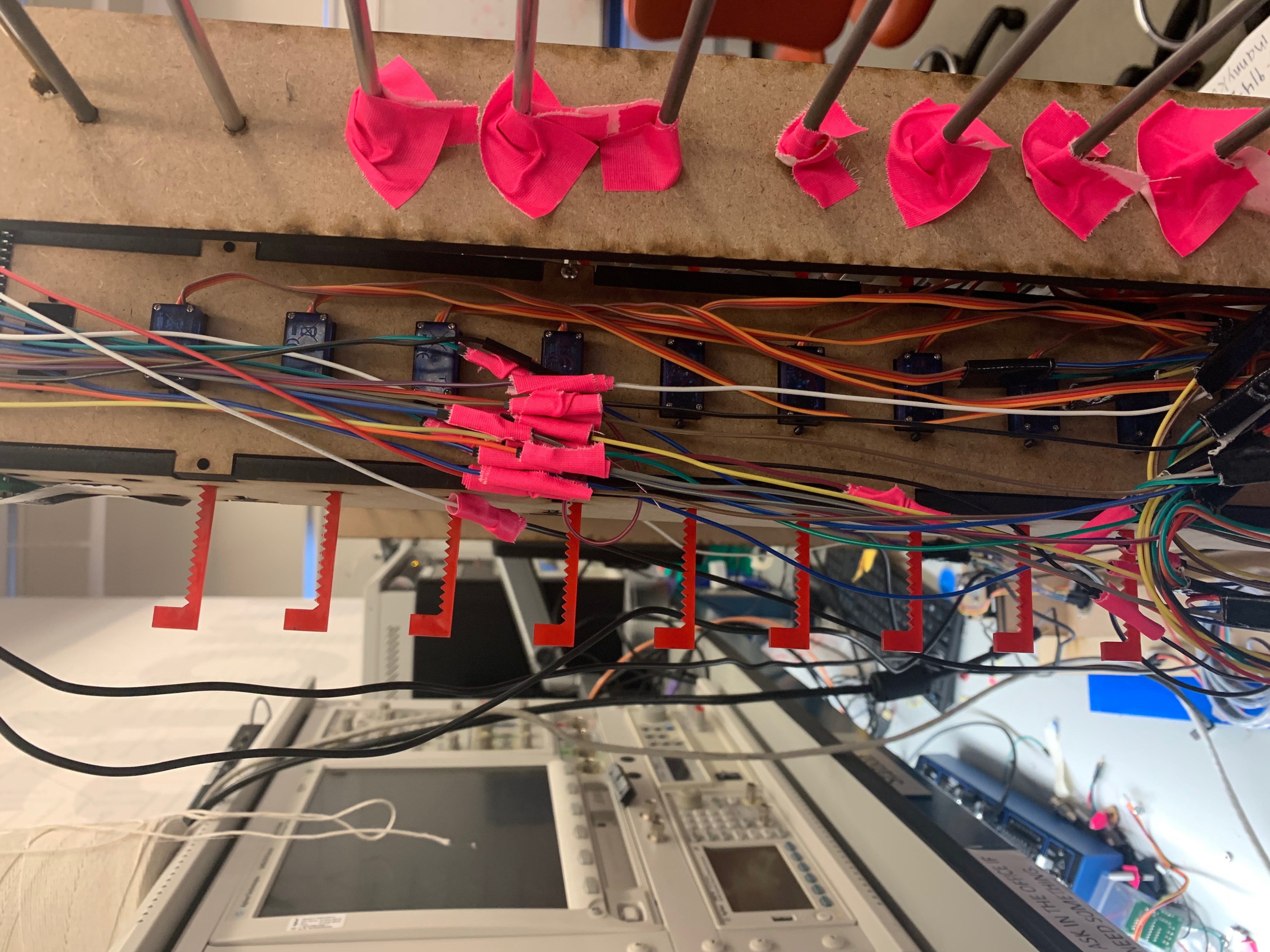
Arm (Idea #3)
In order to reduce the project cost and complexity, rather than attach a servo to each tile, we designed a mechanical arm in Solidworks that would travel across the tile display and push each column of tiles one at a time. This arm was to be made of 1/4" MDF with14 linear actuators composed of 9g micro servos and custom 1/8" acrylic gears. The base of the arm had holes for a timing belt that would connect it with a stepper motor to finely control the distance it needed to travel. However, we were running out of time. Rather than spend a few days fine-tuning the arm's design in Solidworks, we took Dr. Mangharam's advice and "jumped right in" to building and testing as we went. Because the laser cutters were not perfect, this ended up saving us hours of time; some of our pieces needed to be correct down to the millimeter and, in practice, the laser cutters are not that precise.
Now that we had a solid design for the mechanical arm, it was time to begin preparing for the baseline demo.
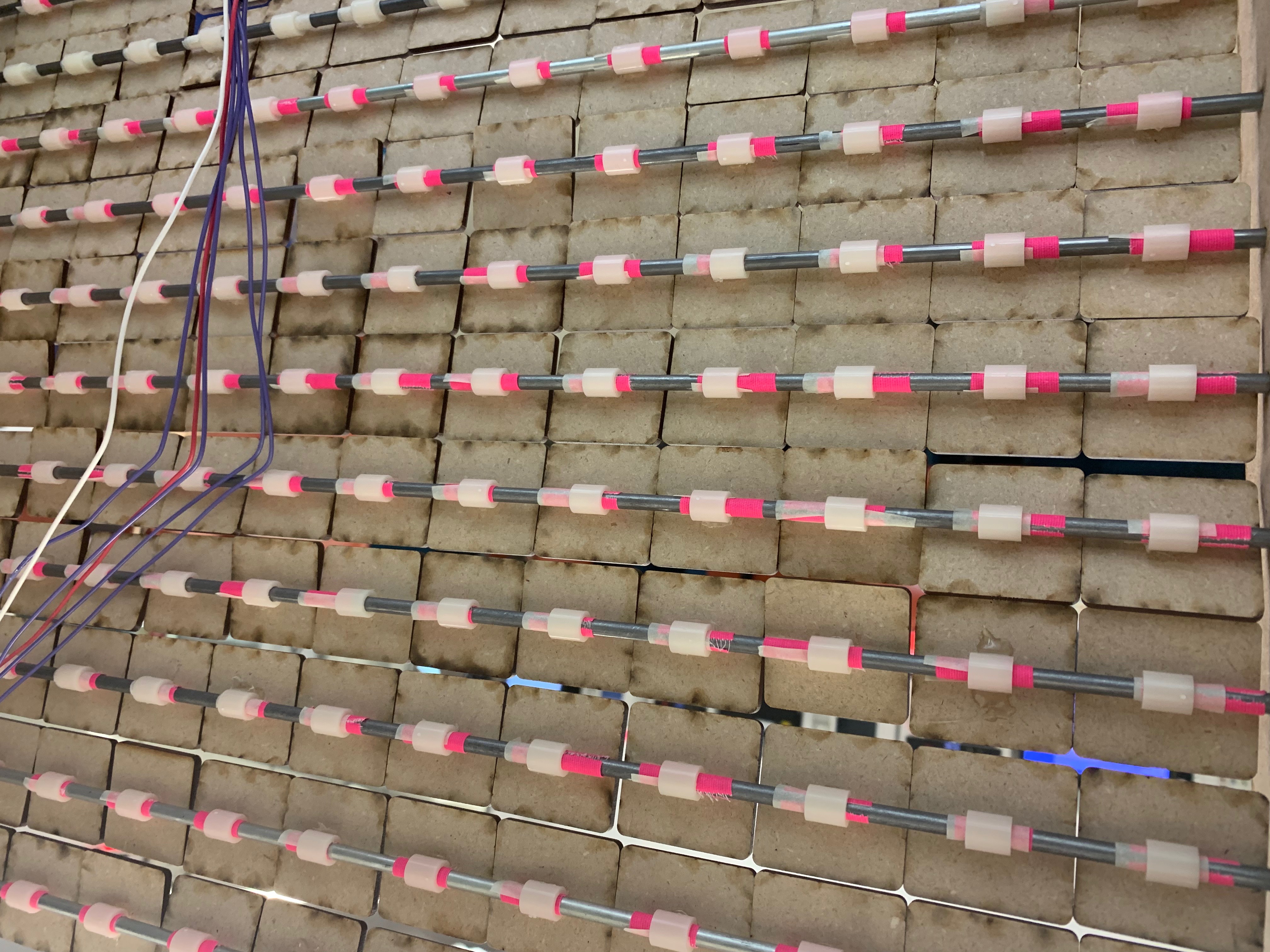
Tiles
Designing, cutting, and preparing the tiles took Manny 20+ hours of continuous work.
Baseline
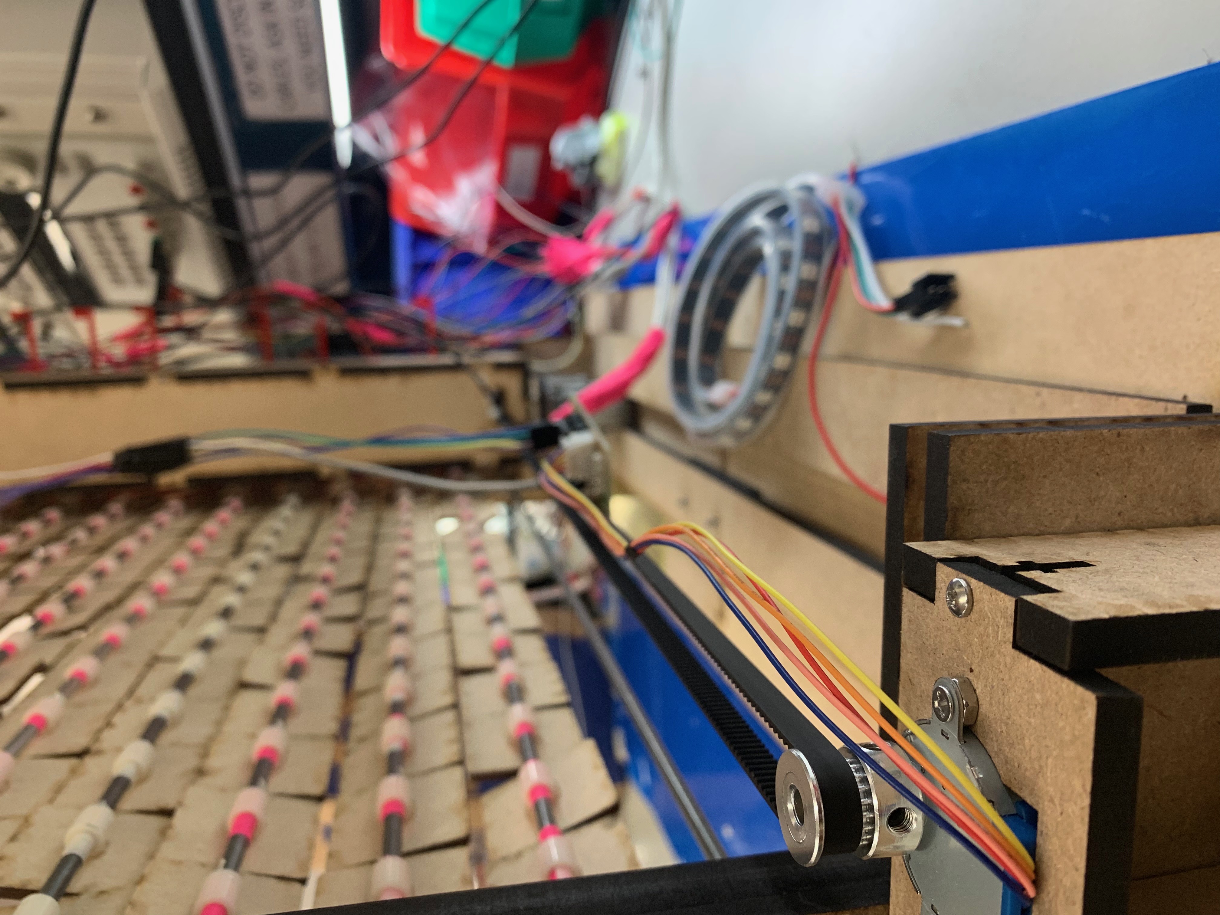
For the baseline demo, we were able to control the stroke of all fifteen linear actuators using raspberry pi, we could move the stepper motor using an Arduino (for rapid testing), and we had a 17x17 grid of 1.5" MDF tiles (with two rows and columns as a stationary border). However, we had not yet integrated all of the systems we had in place. This meant that we were also unable to test/debug the code we wrote to store a displayable image in a 2D array.

Reach Demo
For the reach demo, we successfully completed all of our baseline and reach goals. For the baseline, we integrated the mechanical arm with the stepper motor / timing belt.

To complete the reach goal, we first added a camera to our Raspberry Pi. Then we added OpenCV, an open-source computer vision library, that allowed us to create a separate script that detects whether or not an individual is smiling and stores that information in a text file. This way our original program can run this python script (by executing an operating-system command), read the text file, and print a smiley-face if we detected a smile and a frowny-face if not. We also mounted an LED strip to the top of our frame so users can better see our display.
You can find a video of our final demo here: link
Built With
- c
- camera
- micro-servo
- open-cv
- raspberry-pi
- solidworks
- stepper-motor

Log in or sign up for Devpost to join the conversation.