Inspiration
One of our group members couldn't play the piano, so we wanted to help him out, so we decided to develop a piano playing robot. So he or the robot could play the piano instantly. We also believe that we wanted to reclaim old technology, so we used several old parts like an 1983 Casio MT65 piano and also initially an old power supply from a laptop. Now days, people listen to music via online streaming platforms like Spotify, and we wanted to bring the more physical environment of sound, so we decide to do this with a self playing piano. Initially the idea came from one of our group members who wanted to use an FPGA to convert sounds via the phone output to be played on the piano with the solenoid.
What it does
It allows the user to pick a select number of songs and it will play the song automatically on the middle octave, going from middle C (C4) to B that follows next (B4).
How we built it
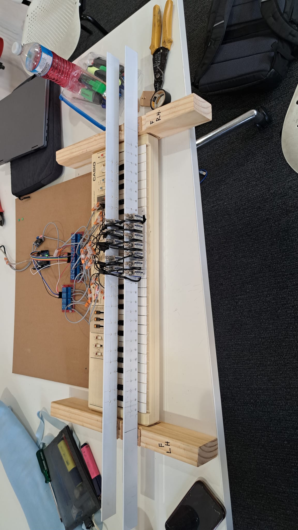
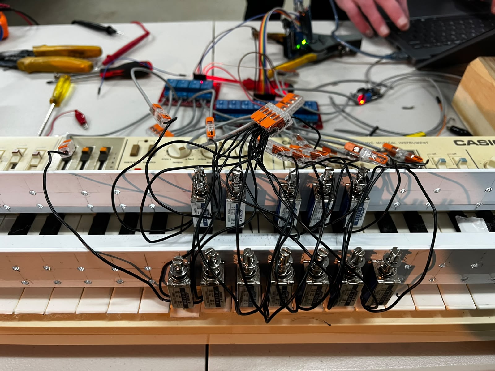
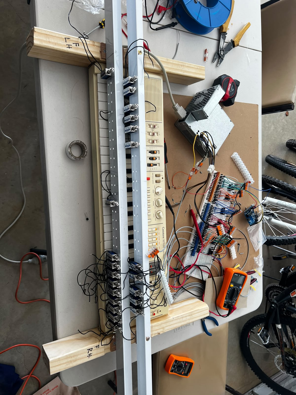
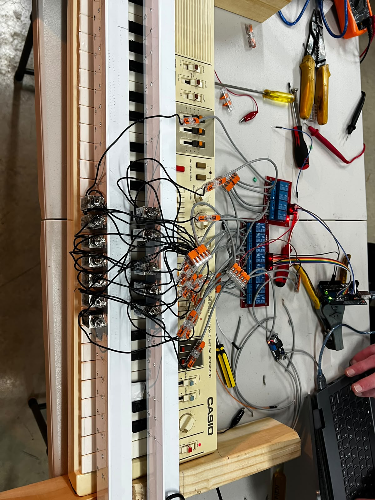
We used an arduino to use the serial to take in the notes that need to be pressed, and then it puts a 5V to the corresponding pin for each key to push the solenoid down on the driver board. The solenoids are then mounted to a L-shaped angle bracket, which is then secured to two wooden blocks which hold the piano in place. Furthermore the current design using an old PC power supply from a HP laptop, which we stripped the cable for, we needed a bulky because the solenoid use 12V, 600mA, so if we need to drive 3 or 4 solenoids, that is 1.8A or 2.4A of current which is quite high compared to other low level electronics projects. This laptop power supply had to be put through a buck converter (which we soldered together), which had to take the 19V laptop power supply and drop it down to 12V to drive the solenoids and the driver board efficiently.
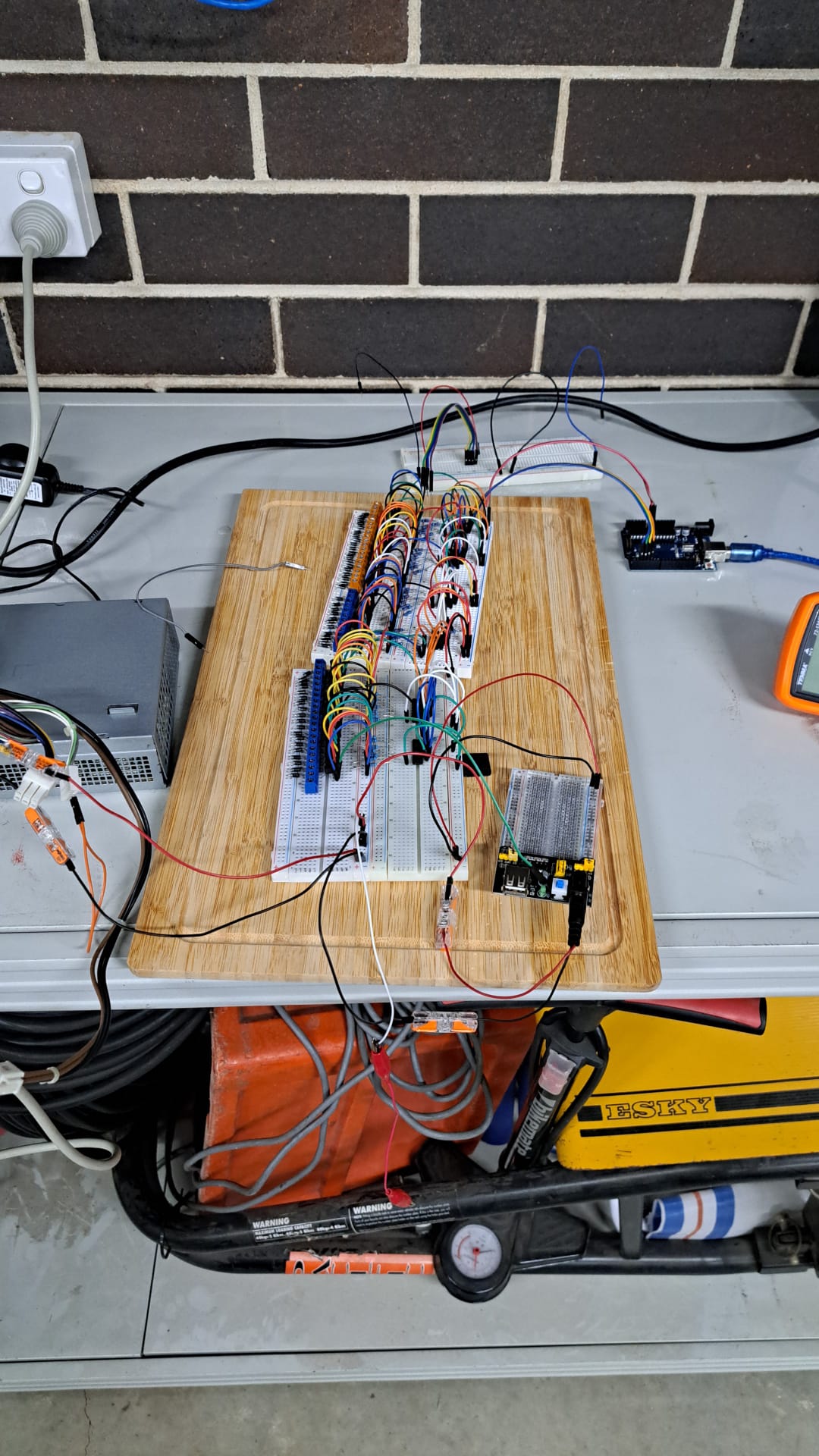
The first prototype was just the arduino wired up to LEDs to show that the MIDI to serial conversion was working. The lights would light up to correspond with the key that is being pressed. Then we purchased the solenoids, and discussed how we would setup the the frame to mount it. When I went through many different prototypes including trying to use a clamp to secure it to the piano. We also initially designed a 3D printed bracket to hold the solenoids, but later opted for a L angle bar. The second stage was using transistors to switch the solenoids, but ultimately this didn’t work. We wired up a whole breadboard with the transistors and PCB block to switch the solenoids, and lots of jumpers to connect everything together. But this approach didn’t work.
The final stage was when we switched to relay, we were too ambitious at the start of the project, and when the hackathon was coming to the nail end, we had to narrow the scope, so we just opted to try and get 1 octave wired up with 12 keys, and use a more reliable way of switching which was with relays, instead of the transistors that were doing us trouble.
Challenges we ran into
The main challenges that we ran into included the incorrect usage of transistors over established relay boards and the initial issue of how to convert MIDI data into python comprehensible code. These challenges also provided valuable lessons which we will also cover. Other challenges involved the creation of a sturdy frame for the solenoids and also which solenoids to choose and a cheap provider to source them from.
The problem with the transistor was that we didn’t have enough base current going into the transistor to switch into steady on state, instead it was stuck in the linear region, where it was dropping lots of voltage and acting like a dimmer. We tried different values of resistance but even if went lower, to get more current, which by the calculation of the gain of the transistor, we need 60mA of current, but the shift register IC, we were using, it was rated for only 30mA per pin, and 100mA for the whole chip, so it wasn’t possible to achieve what we needed. We thought about using MOSFET however they were too expensive and we were out of time, so we went with relays.
For the frame we decided to simply build one, with one of our team members utilising L-frame extrusions and simple wooden blocks to create the base and bracket that sits directly on top of the keys. We did this because we tried to 3D print but we didn’t have access to the machines to do so, so it was easier to construct it manually. The solenoids were sourced from alibaba as domestic sources proved too expensive and impractical considering also they also had longer delivery times.
With the breadboard, initially there would we were going to power all the solenoids through the power rail, but after doing some research we found that the breadboard power rail can only handle 2-3A, so if we tried to do that we melt the plastic and the traces would break. So instead we took jumper leads out of the breadboard bus into Wago and use high guage wire for household electrical work to share the load so the breadboard wouldn’t fry itself.
Some other challenges include wiring up the IC for shift registers, sometimes we got the wiring mixed and the signal wouldn’t send so we spent hours debugging that, it would have been better to just look closely at the datasheet to get it working. Also throughout the project we blew up countless transistors that we had to replace, which didn’t cost a lot at least.
The final challenge we had was that we initially started with a power supply from an old desktop supply at Josh’s work (we wanted to recycle old components), when we brought it home, we took out the fan because it too loud, it was rated for 12V 16A so it would have been perfect for the amount of solenoids we were going to use (initially the whole piano). But after a lot of testing, we found out that when we had a load of more than 2 solenoids the power supply kept dipping up and down and couldn’t sustain a the load. We scratched our heads for a while trying to figure out what was wrong, but at the final straw, we decided to change the supply to a HP laptop power supply rated for 19V and about 2A, and then we used a buck converter to put it down to 12V. This fixed the problem, and it really was the pinnacle in solving the project.
Accomplishments that we're proud of
I would say for the biggest accomplishment was getting our group together, we all have differing schedules, so it was a challenged to everyone together to work on the common goal and build this piano, but I think we did extremely well to finish what we did in two weeks, and have shared spaced to work on this was the most important part.
The first real accomplishment was when got the LEDs working to play the song via the keys being pressing, when those lights lit we saw the path that we needed to reach the goal. It was like we only a few more steps to do and we could get piano playing, but really little did we know it was much harder than we thought.
Really the second accomplishment was probably getting the solenoids, because that when it became real, we had already made the bracket and start the circuity using the transistors, but when the solenoids came which they came in the last week, it looked like it was coming to life.
Then it was playing one key and then two keys, and then three, keys, but at that point we hit a brick wall because the transistors and the old desktop power supply we got didn’t handle our goals, so we were stuck scratching our heads.
Finally, the best thing was when it played Mary Had a little lamb, we know it may not sound too impressive compared to what you saw in the video, but really when all the keys were playing in order they were meant to it, felt like we had reached the top.
Then on the last day of the hackathon, we got Rush-E playing, which is notoriously a difficult song for piano players, and that really put everything together for us.
What we learned
The majority of our early prototyping was centred around the use of NPN transistors to control the signals coming from the arduino. Although preliminary operations were successful - with individual solenoids enabling reliably, we encountered inefficient performance from the solenoids when enabling two or even three solenoids. In some instances solenoids would be jerky, some wouldn’t enable and transistors would burn up. Upon further investigation we found various limiting factors involving current being driven, missing bypass capacitors and unreliable voltages being seen by the solenoid. We learnt that MOSFETs would have been ideal for this scenario given its lesser reliance on current, however considering budget and time constraints, we opted to use relays, replacing our transistor based prototype.
We also learned valuable insight to the world of MIDI parsing and MIDI programming as a whole. Upon further research we found that there were various approaches to our project’s end goal, mainly involving MIDI breakout boards and MOSFETs to convert MIDI data. We took inspiration from these methods and adapted our approach to fit our constraints.
What's next for Pi’erre The Pianist
We really want to continue the project in the future, because we didn’t get to completed it to what we initially set out to do. Initially we wanted to do all the keys on this piano which is 49, but eventually we want to scale it to a full 88 key piano, and also a PWM modules so that we can use weighting of the keys being pressing down to different stroke lengths. Even additional controls for the pedals would be good.
There is still some mechanical bugs than we need to fix up, and we want to try and make the sound of the clicking of the solenoid, much softer so it doesn’t drown out the music, we though the best way to do this was to, use rubber O-rings or rubber bands around the solenoid to soften the stroke.
Furthermore, our electrical engineering friend at RMIT, Cass, said he wanted to design a PCB for the project, to make a smaller form factor and clean up some of the cabling. This also allows us to add more electrical components that would be needed like putting the buck converter on the PCB, and the flyback diodes on the board, etc and maybe utilising Mosfets instead of transistors.
To make it more versatile if we could design a better bracket or mounting mechanism to clip the piano so that we can really just set this up on any piano and it will work almost instantly would be really exciting.
And again, the final goal of the project was that you could connect your phone in via a 3.5mm headphone jack or bluetooth, and that it would use a FPGA, to apply a fast fourier transform to sound to extract the different notes from their frequency and play the song in real time. This way it gives the user more options to what to play and it is very seamless in terms of what the user can do.
Ultimately, these are all grand ideas, and a small subset of what we wanted to do, but we like to set high goals, and get as close as we can to achieving it, and our team did a magnificient job to produce such high quality work in a small period of time. We are all very passionate about this project and we hope to continue it into the future and build and expand upon. The Hardwired hackathon gave us the inspiration, the time and the community to build the first edition, but we know there will be many editions to come.
Built With
- aluminium
- arduino
- blood
- buckconverter
- hardwork
- ide
- jumper
- keyboard
- kfc
- piano
- powersupply
- relay
- screws
- solenoid
- sweat
- tears
- timber
- transistor
- wago
- wire

Log in or sign up for Devpost to join the conversation.