-
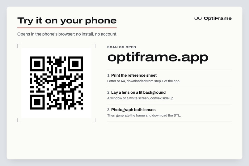
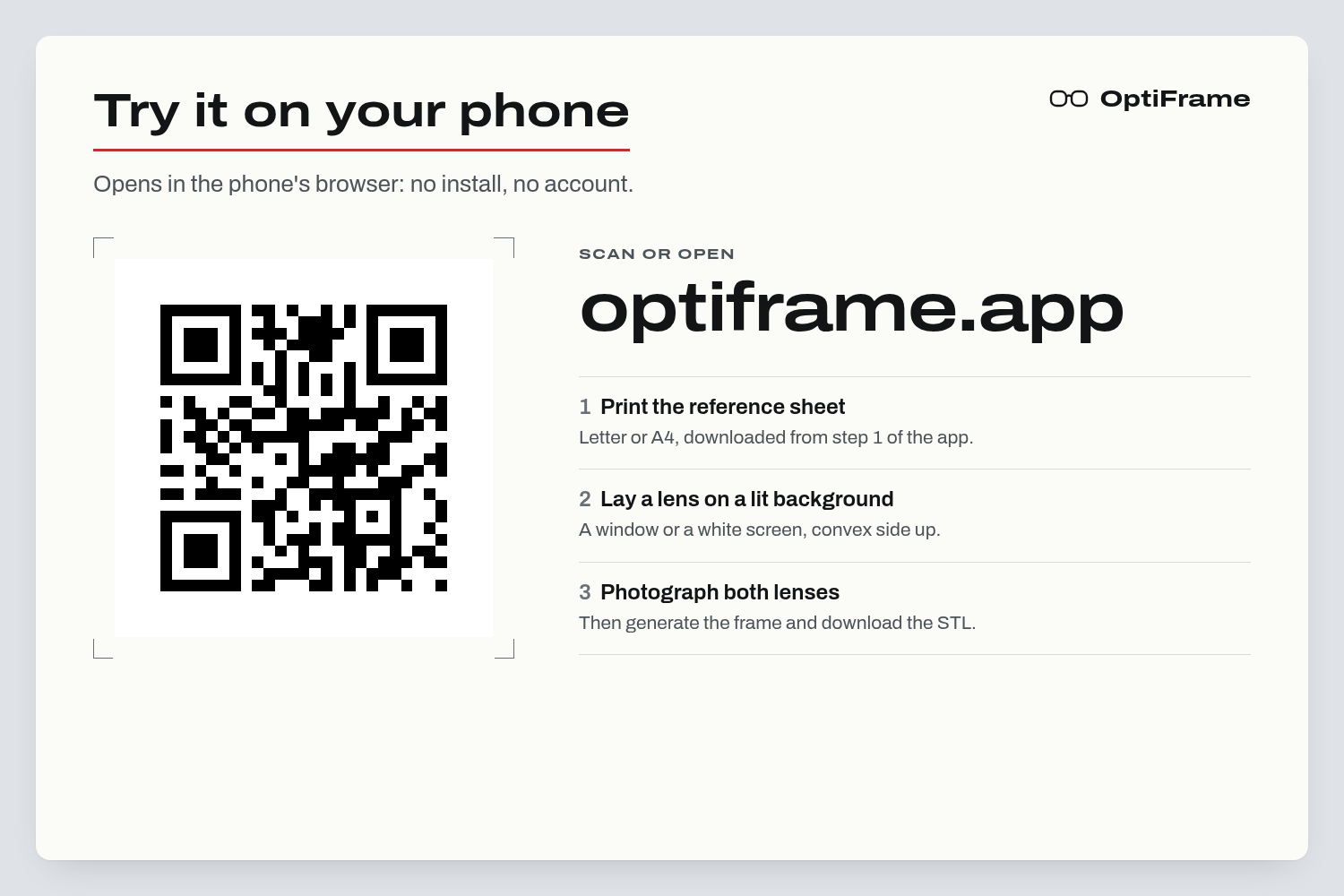
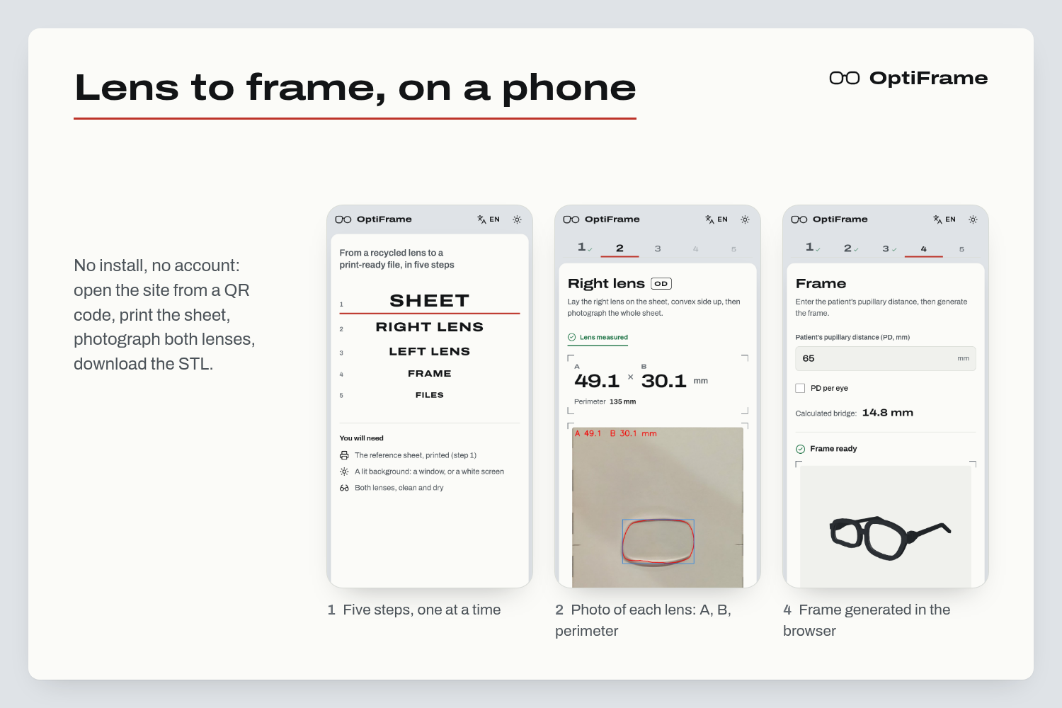
Scan to try OptiFrame on your phone at optiframe.app: no install,no account. Print the sheet and photograph a lens.
-
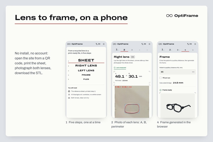
The whole flow on a phone, with no install or account: print the sheet, photograph each lens, generate the frame and download the STL.
-
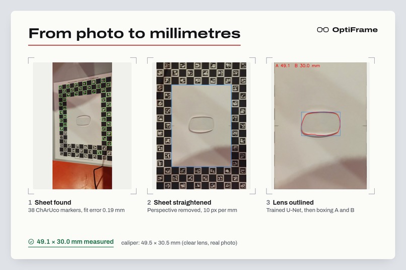
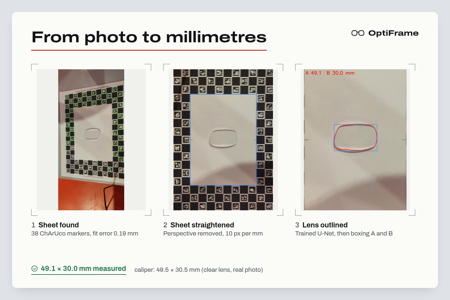
Real photo to millimetres: sheet found, straightened, lens outlined. 49.1 × 30.0 mm vs 49.5 × 30.5 mm by caliper.
-
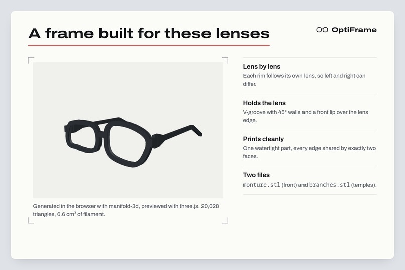
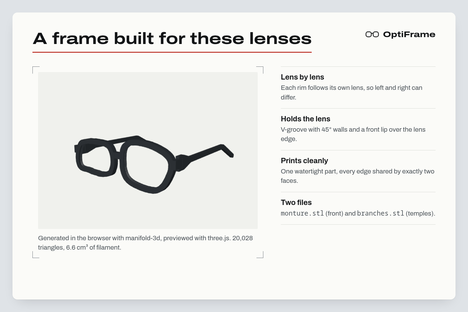
Frame built in the browser for these two lenses: each rim follows its lens, one watertight part ready to print.
-
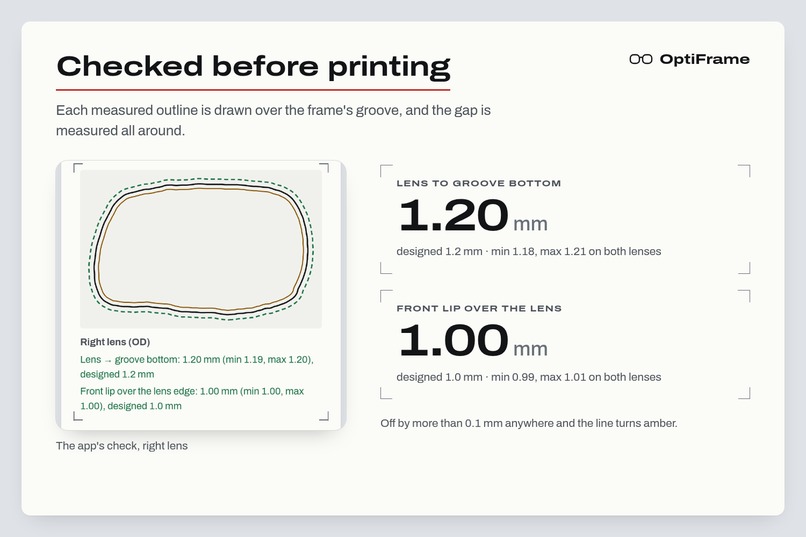
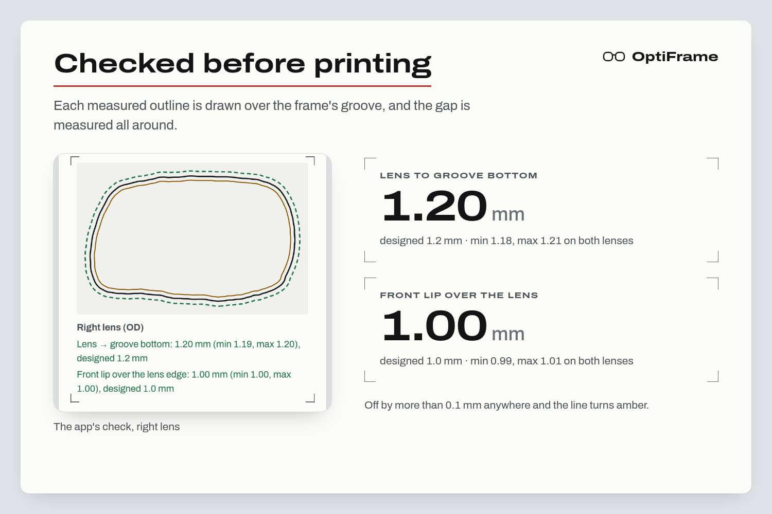
Checked before printing: each lens outline over the frame's groove, gap measured all around, as designed.
-
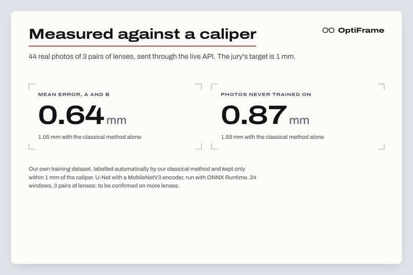
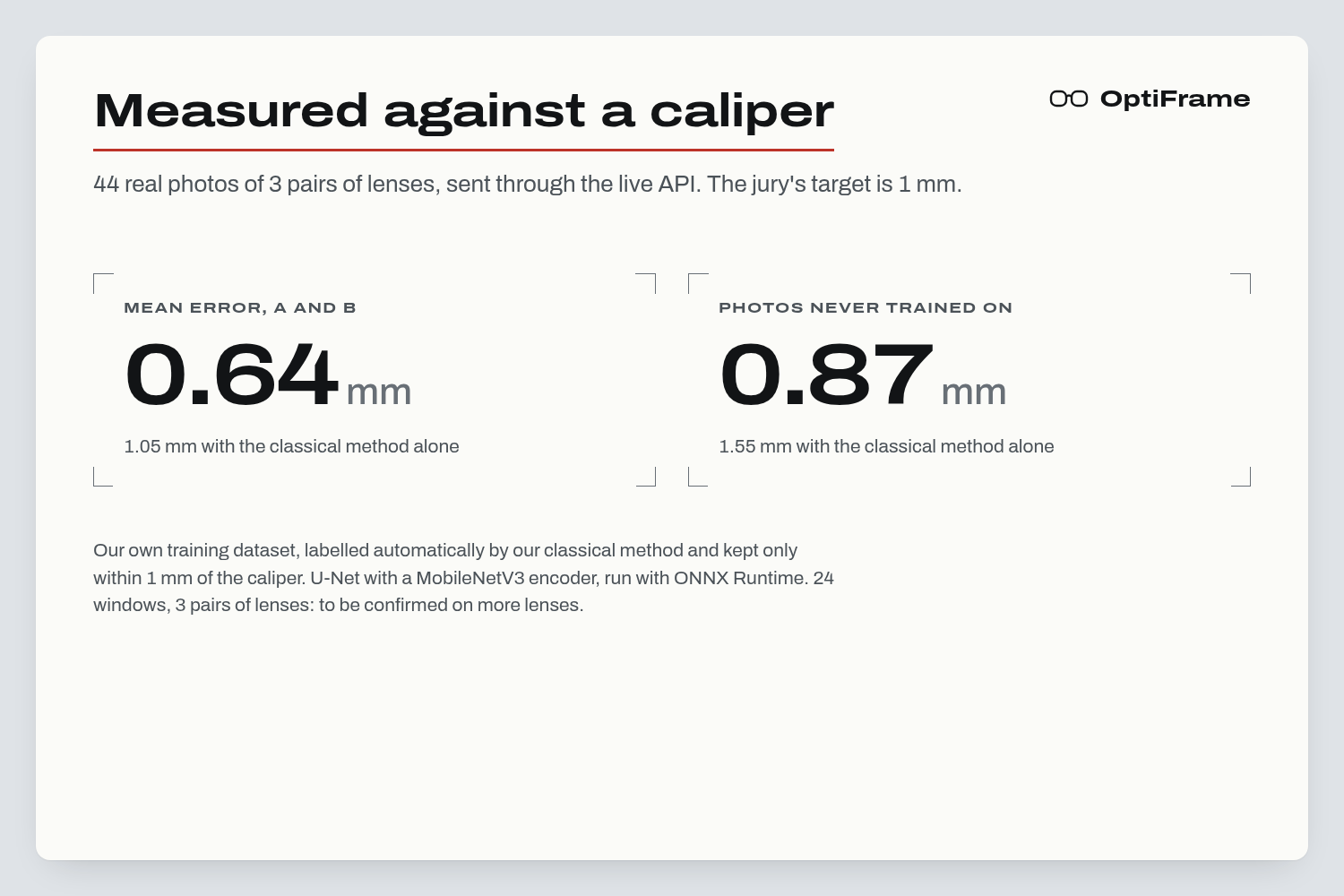
0.64 mm mean error vs a caliper on 44 real photos. Model trained on our own dataset, labelled by our classical method.
-
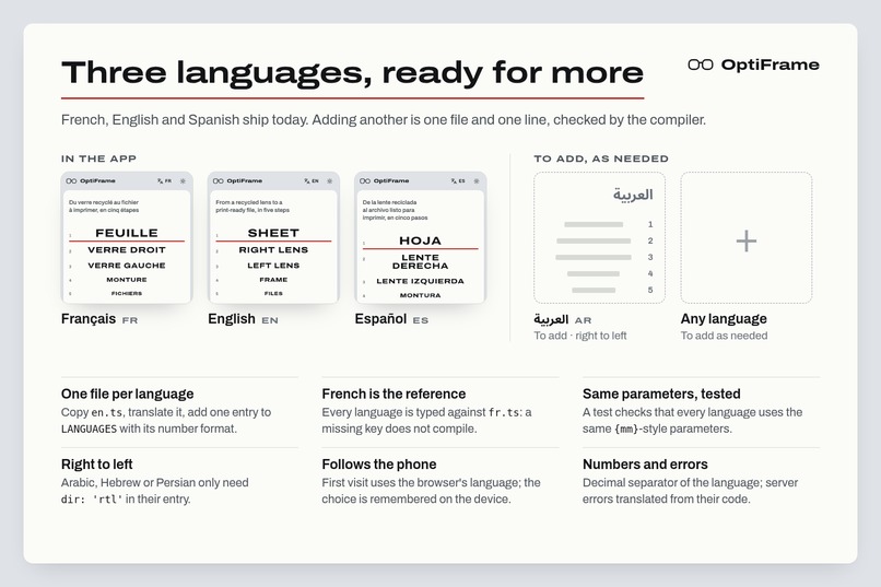
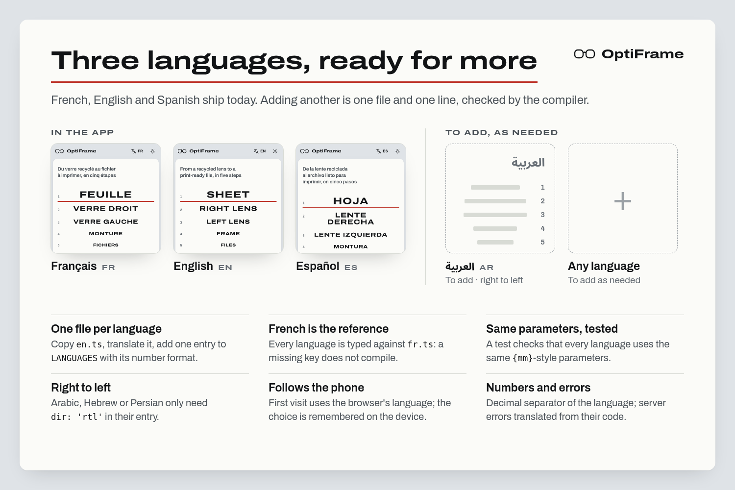
French, English and Spanish today. Each new language is one file checked by the compiler; right-to-left ready.
Inspiration
OptiFrame is our answer to the Santé Numérique Sans Frontières challenge at CodeML 2026. Clinics, fablabs and local organizations often have recycled lenses on hand, but fitting them to a new patient needs a frame cut to their exact shape, and that takes an optician and equipment they don't have. OptiFrame replaces both with a printed sheet, a phone and a 3D printer.
What it does
- Print a reference sheet (Letter or A4) and lay the lens on it, convex side up, lit from below (a window or a laptop screen works).
- Photograph the right lens, then the left one. The app returns the boxing dimensions A (width) and B (height), the perimeter, a control image of the detected outline, and a 1:1 SVG contour you can print and lay the real lens on.
- Enter the pupillary distance (or use the standard 18 mm bridge) and generate the frame. It is built in the browser, lens by lens, so the left and right rims can differ. Download
monture.stlandbranches.stl(the temples) for a 3D printer.
Extras: a fit check that draws each lens outline over the frame's groove with the gap measured all around, a coherence check between photos of the same lens, an approximately true-size try-on on your face, and French, English and Spanish.
How we built it
Scale and perspective. The sheet is a ChArUco board: a checkerboard with ArUco markers, around a plain window for the lens. OpenCV finds the corners to sub-pixel accuracy and fits a homography $H$ that maps the photo to the flat sheet:
$$ \begin{pmatrix} x' \ y' \ 1 \end{pmatrix} \sim H \begin{pmatrix} x \ y \ 1 \end{pmatrix} $$
The lens window is rectified at 10 px/mm, so a pixel count becomes millimetres directly.
Finding a transparent lens. A clear lens on a white sheet is almost invisible. Two segmenters run on the rectified window:
- a classical one: a polar contour search from the lens centre that follows the rim, with a smoothing pass;
- a U-Net (MobileNetV3 encoder, 512 × 512) exported to ONNX and run by the Spring Boot API.
The model was trained on windows labelled by the classical method, but only when its outline matched the caliper within 1 mm on both A and B. That left 24 training windows (23 automatic labels, 1 traced by hand). On 44 caliper-measured photos of our 3 lenses, the mean absolute error on A and B went from 1.05 mm to 0.64 mm (0.87 mm on photos the model never saw), and photos within 1 mm on both went from 19 to 29 out of 41.
The frame. The frame front is generated in the browser with manifold-3d: each lens outline is offset into a rim with a V-groove (45° walls) designed to hold the lens, joined by a bridge and hinge lugs. The temples are a separate printable part. A three.js preview shows the result before download.
Face try-on. MediaPipe Face Landmarker tracks the face on the device, and the image never leaves the phone. The scale comes from the iris, whose visible diameter is about 11.7 mm in adults:
$$ \text{mm per pixel} \approx \frac{11.7}{d_{\text{iris, px}}} $$
so the frame is drawn at about true size with no reference object (iris size varies by roughly ±0.5 mm between people, about ±4 % in scale).
Stack. Angular PWA, Spring Boot + OpenCV + ONNX Runtime, PyTorch (segmentation_models_pytorch) for training, deployed as a single image on Google Cloud Run.
Challenges we ran into
- The shadow is darker than the lens. Our first segmenter traced the lens's shadow, up to +4 mm on A. We re-tuned the thresholds on real photos and added a regression test built from that exact failure.
- The printer lied. Our measurements were all about 2 % too large. The sheet had been printed at 97.87 % even at "100 %" (5 squares measured 73.4 mm instead of 75.0).
- Parallax. The lens edge sits a few millimeters above the sheet, so it looks bigger. For a camera at distance $D$ and an edge at height $h$, the magnification is about $1 + h/D$: around 1 % at 30 cm, but a steeply tilted shot added 4 mm on B.
- A non-manifold frame. The first STL had 27 separate parts and thousands of edges shared by more than two faces, from a groove cut as a stack of thin slices. Cutting the groove as one smooth solid gave one watertight part, 19,674 triangles (down from 97,990), with every edge shared by exactly two faces.
- Ideas that didn't pan out. We tried Segment Anything: it works with a box around the lens (IoU 0.96–0.98) but fails with point prompts or in automatic mode. We also tried Ronchi (striped) sheets to make clear lens edges visible, but our methods couldn't find the outline on them. No public dataset matches a cut lens alone on a sheet, so we built our own.
Accomplishments that we're proud of
- A printable frame, not just a measurement. Photos go in, one watertight STL comes out (19,674 triangles, every edge shared by exactly two faces), with the left and right rims each cut to their own lens.
- Two segmenters, one fallback. The model is used by default and the server falls back to the classical method when it's missing, so the app always answers.
- Privacy by design. The face try-on runs entirely on the phone; no face image is uploaded.
- Numbers anyone can check. Every measurement comes with a control image, a 1:1 SVG and a fit-check overlay, in French, English and Spanish.
What we learned
- Measure early. Synthetic tests said we were 0.2 mm off. Real lenses with a caliper told a different story: the shadow, the print scale and the tilt. Each one was invisible until we compared against the caliper, and the same comparison set the final edge correction: the model read A and B 0.25 mm too large on 45 photos, so we shrink the outline by 0.1 mm.
- Clean labels matter more than many. Gating auto-labels on caliper agreement gave us usable masks from only 24 windows, though 3 lenses is far too few to generalize.
- Make every number checkable. Control images, the 1:1 SVG and the fit-check overlay let someone without an optician's training trust, or question, the result.
Built With
- albumentations
- angular.js
- docker
- google-cloud-run
- java
- manifold-3d
- mediapipe
- numpy
- onnx
- onnxruntime
- opencv
- pwa
- python
- pytorch
- segmentation-models-pytorch
- spring-boot
- three.js
- typescript


Log in or sign up for Devpost to join the conversation.