-
-
-

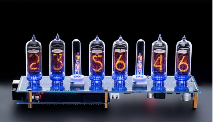
tube testing
-

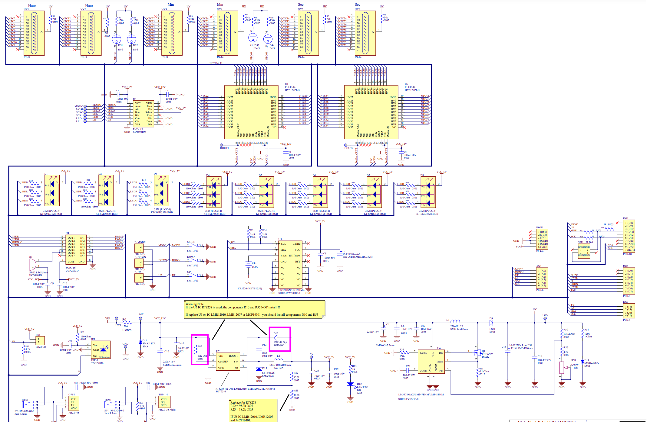
schematic


Inspiration
Since both of us are fans of cyberpunk, one day we happened to see this fantastic displaying tube called Nixie tube on the Internet. The Nixie tube contains a wire-mesh anode and several cathodes shaped like numbers. The tube is filled with neon gas at low pressure. When about 170V voltage is applied between anode and cathode, the corresponding numerical shaped wire is lit up. Nixie tubes were widely used during the 1960s and they are rarely seen in today’s applications. However, its soft orange light often reminds us of the past golden years for the electrical industry. Thus we decided to use Nixie tubes to build a clock for tributing the past.
What it does
First of all, we would like to realize standard functions for a clock, that is, time, date, alarm clock. When the power is off, the clock should not lose its time data. So we would like to introduce a real-time clock with a battery. Since we have amazing potentials powered by Arduino compared with other modern clocks, we would like to implement temperature measurement and some Entertainment functions. Also, an adjustable background color would make it look more cyberpunk so we would like to add six RGB LEDs to make it come true. Last but not least, it’s the functionality that really matters, so we would like to design a self-test procedure to make sure every part works just fine.
How I built it
For standard clock function, we will need six Nixie tubes, shift registers, buttons for adjusting time, and a buzzer for alarm. Driving the Nixie tube, we will have to use HV5122, which is a low voltage serial to high voltage parallel converter with open-drain outputs. We use shift registers with SPI to implement the static display principle. HV5122 is very convenient because it allows us to simultaneously control three tubes, as a 20-bit register. For real-time clock function, we will choose DS3231, an RTC chip with I2C integrated. The Input voltage is 12V so we will have to generate 5V and 170V voltage using two DC-DC modules, to be specific, the step-down converter using RZ8258 and HV Boost converter using LM3488. For the led color adjustment and buzzer tuning, we choose ULN2003, a high-voltage and high-current transistor array as the control signal reinforcement. For temperature measurement, we choose DS18B20, a temperature sensor.
Architecture
Main function architecture We built an architecture based on the menu position. In order to implement all the functions listed above with only three buttons, we created a circulating root menu with child menus and position flags. By using a variable called “menulocation” we can determine where we are in the current menu. When we enter a child menu, the position index will be automatically incremented or decremented depending on where we go in the menu. All the modes below and their subcategories are predefined in the program.
The root menu has four modes: Time, Date, Alarm and 12/24. By pressing the MODE button, these modes change from one to another in a circle.
Time Mode: The Time mode is the one to be displayed most of the time. If we hold the MODE button for 2 sec, we will enter its child menu where we can adjust time by hour, minute and second. The digits chosen will blink and at this time we can press UP or DOWN to adjust numbers. After time being set, we can press the MODE button to return to the root menu. Also, if buttons are not pressed while tubes selected are blinking, the clock will automatically return to the root menu after 1 minute.
Date Mode: To set a date, we can enter date mode by holding the MODE button for 2 sec and Days will flash. While any digits are selected, we can press UP or DOWN button to adjust numbers. If we hold UP or DOWN button, we can change the numbers at a higher speed. If buttons are not pressed while tubes selected are blinking, the clock will automatically return to the root menu after 1 minute. The clock does make validation for the correct date. So the clock will not return to Date Mode if the date is incorrect.
Alarm Mode: The alarm sounds at the pre-set time every day. We can press any button to stop the alarm when it is playing. In this Mode, we have four sub-modes in the child menu: Hour, Minute, Second, Daily on/off. After entering the Alarm mode, we can adjust the numbers using the method described above. Daily alarm is represented by the two dots between six tubes. By pressing UP or DOWN we can enable or disable the daily alarm, represently.
12/24 Mode: By holding the MODE button, we can enter the 12/24 editing mode, pressing UP or DOWN button can change the 12/24 mode.
LED background Light setting: By short clicking the DOWN button, we can stop LEDs from changing. By short clicking the UP button, we can resume LED color changing. By long clicking the DOWN button, we can turn off all the LEDs. By long clicking the UP button, we can turn on all the LEDs.
Conclusion
This project is a perfect opportunity to review everything we learned in this semester. Since Arduino is a basic CPU, it’s quite challenging to realize all the functions with these limited resources. Besides building each function module, we need to consider the conflicts of shared resources, and find a compromised way to satisfy the requirements of both sides. Also, due to the hardware constraints, we have a chance to explore the realization of I2C and SPI communication protocol, and wrap them into functions. The most interesting part of this project is the music play function. By utilizing modularization , macros, and wrapping everything into functions, we can easily configure the tune, duration, sharp, octave of each note. So everyone can use a descriptive character string to play a song with our customized function. Due to the resource limit, we can’t realize too many functions. If we can use other advanced processors, our design could be fancier.
Next steps
For the next step, RTOS can be used to deal with shared resource conflict. That would be an easier and more stable way to arrange assignments.

Log in or sign up for Devpost to join the conversation.