-
-
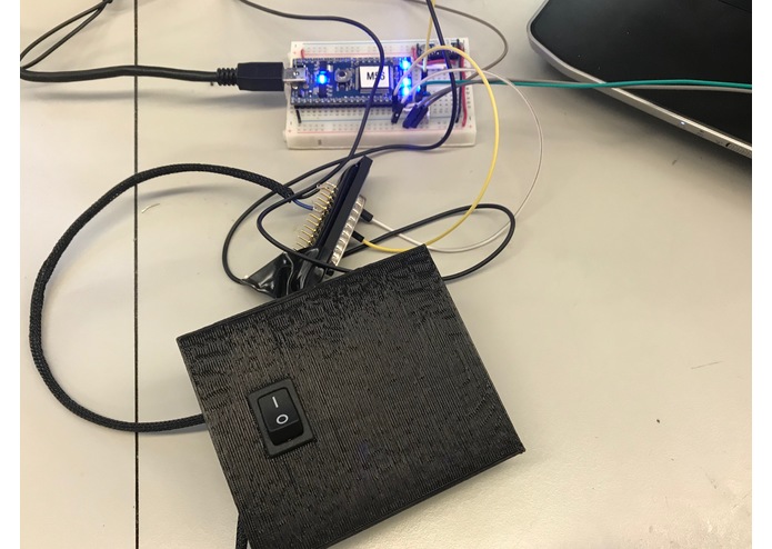
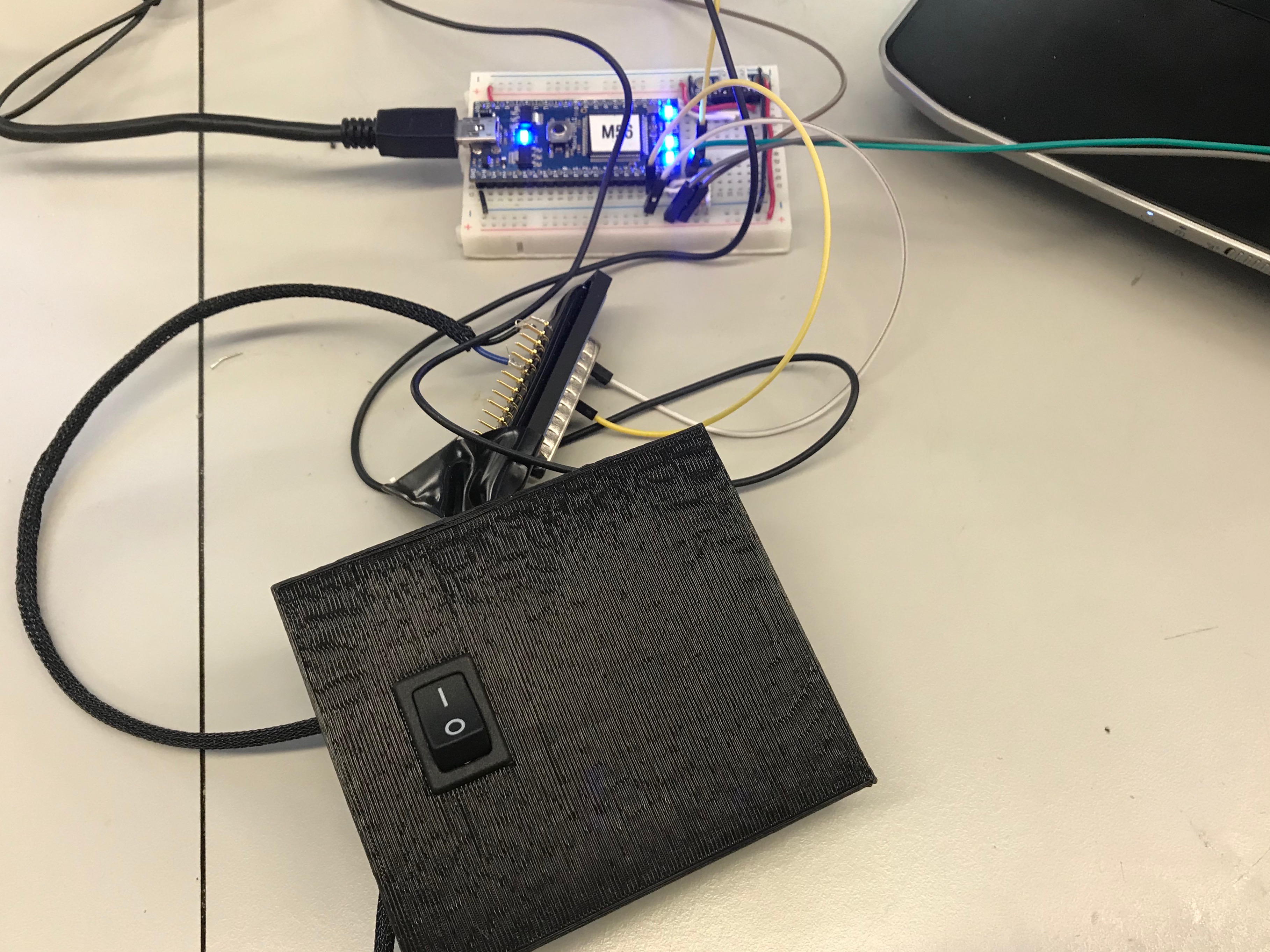
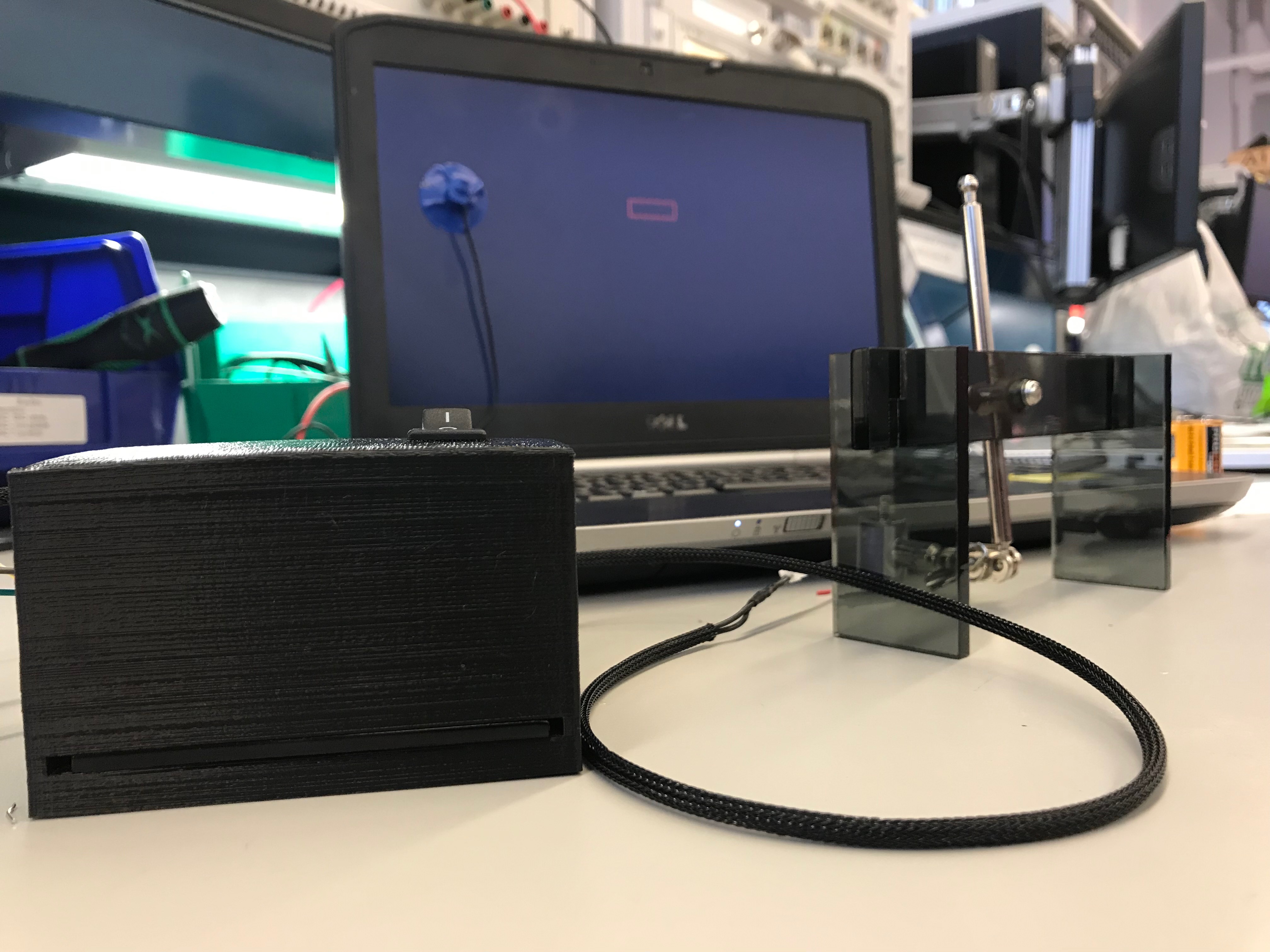
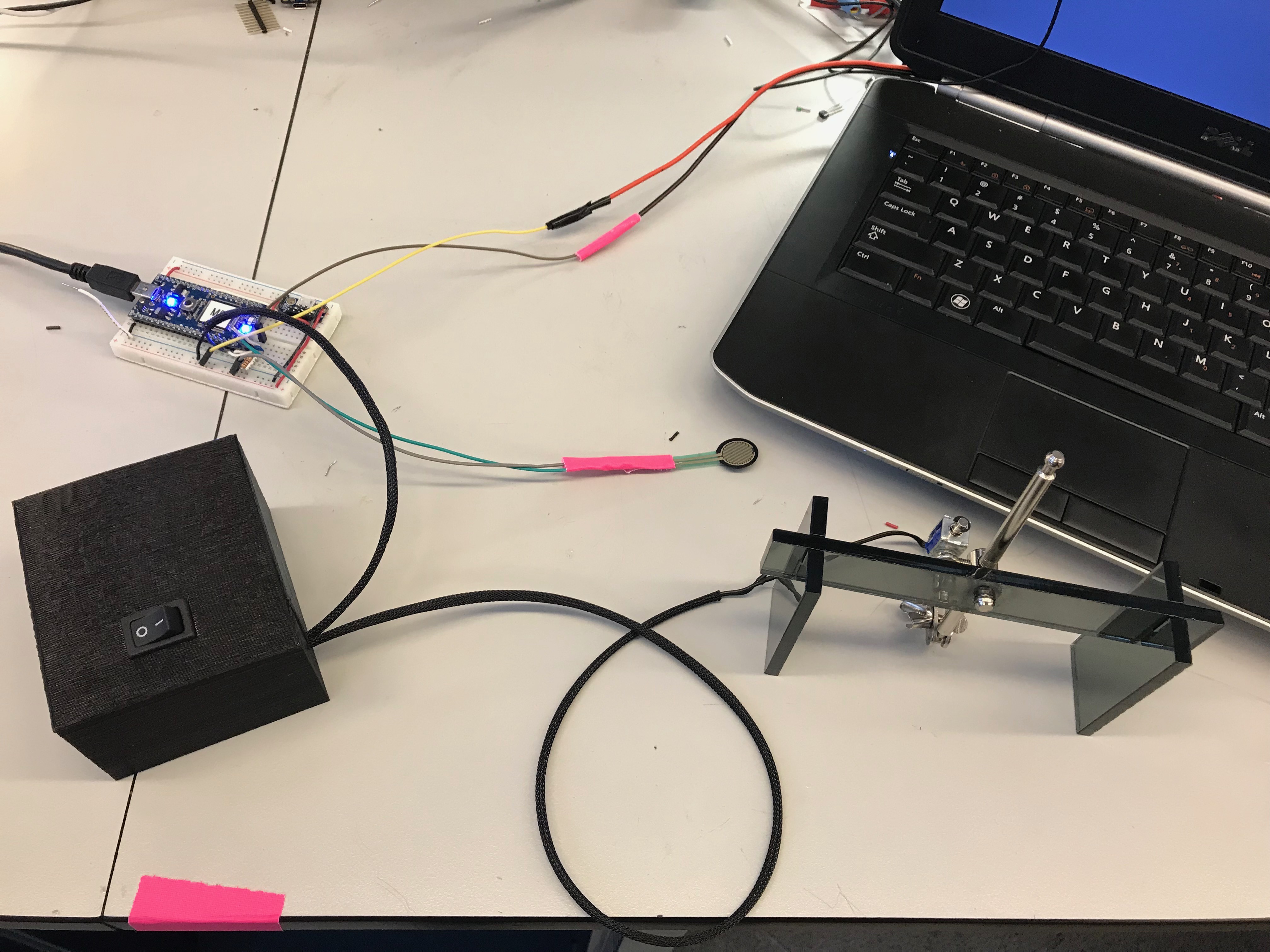
Mbed and box with batteries and solenoid control circuitry
-
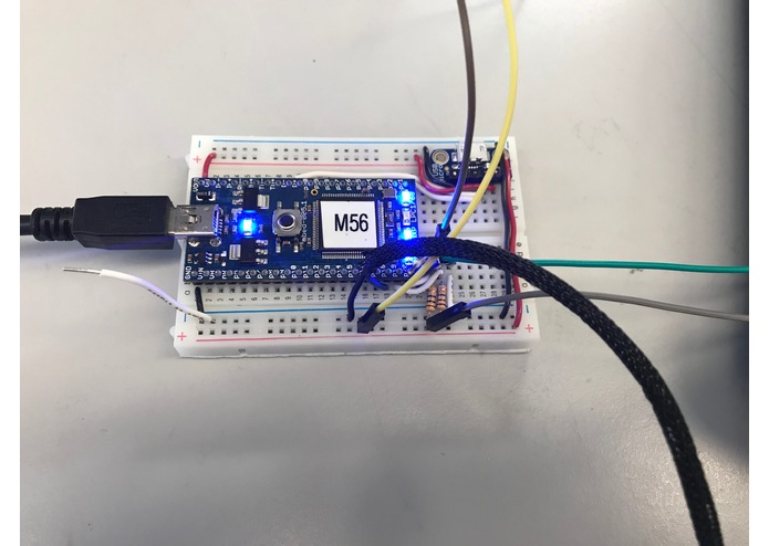
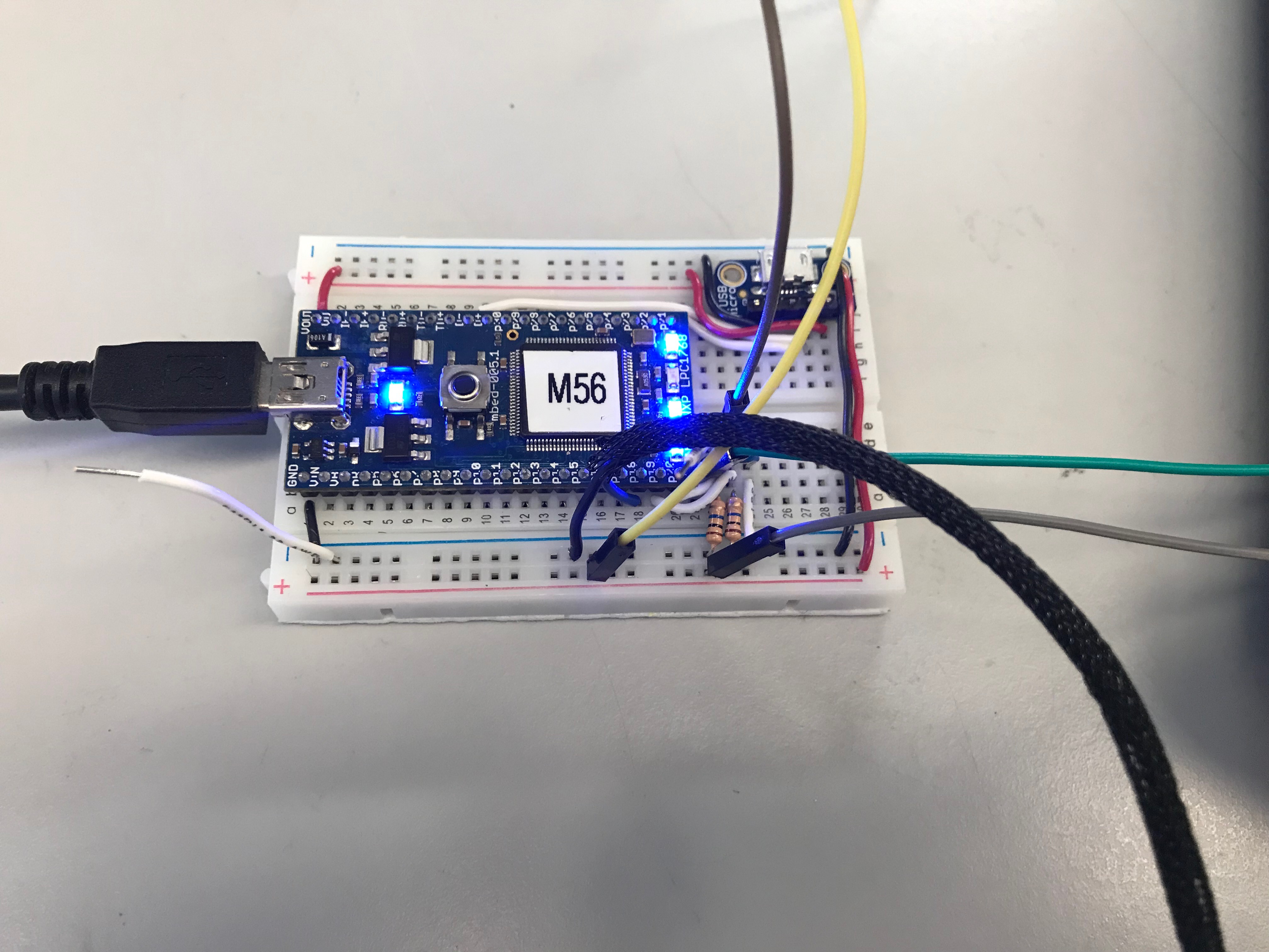
Mbed
-
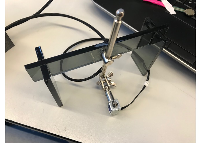
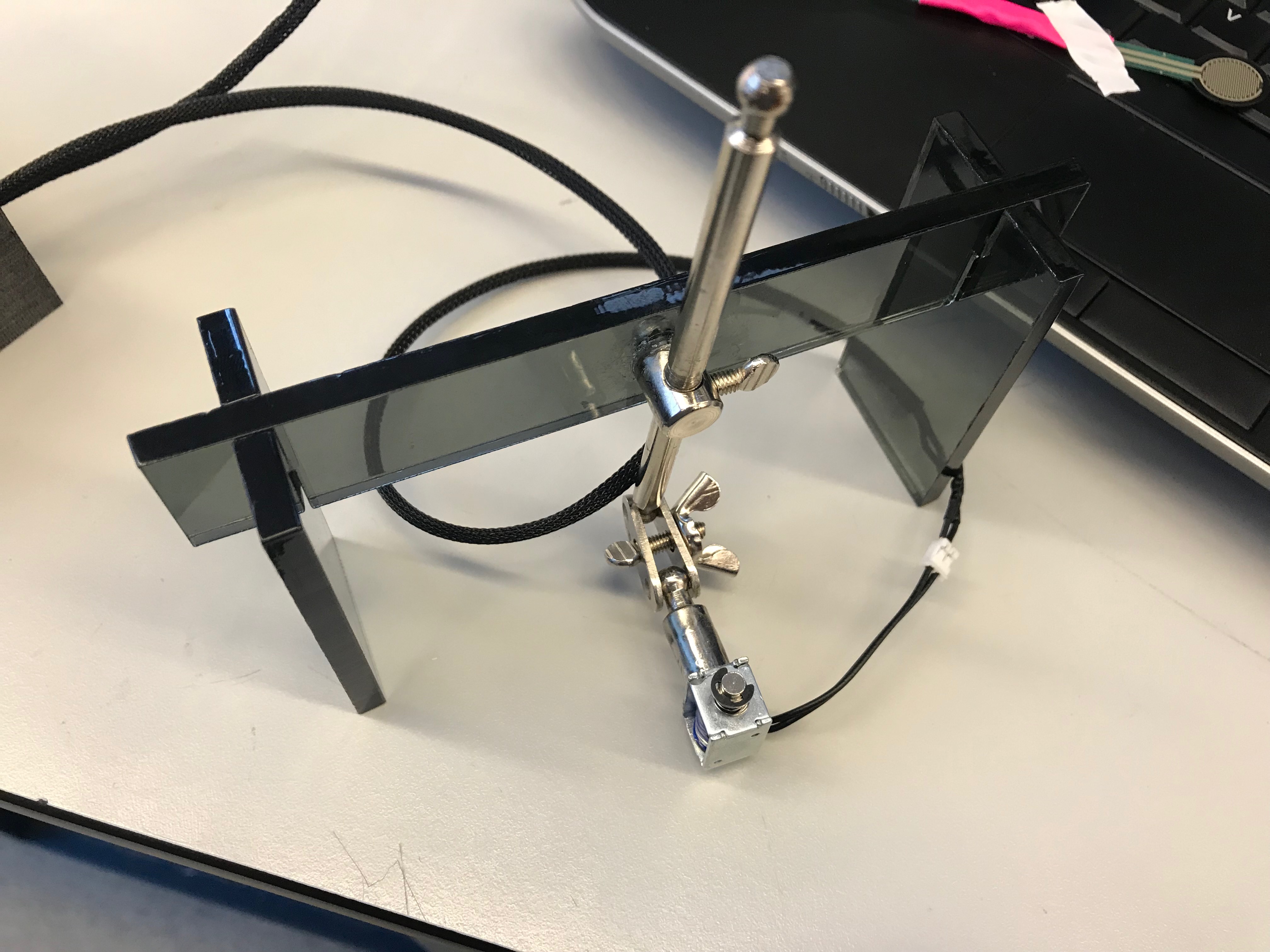
Stand with Solenoid
-
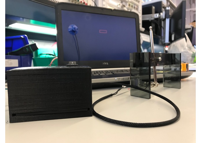
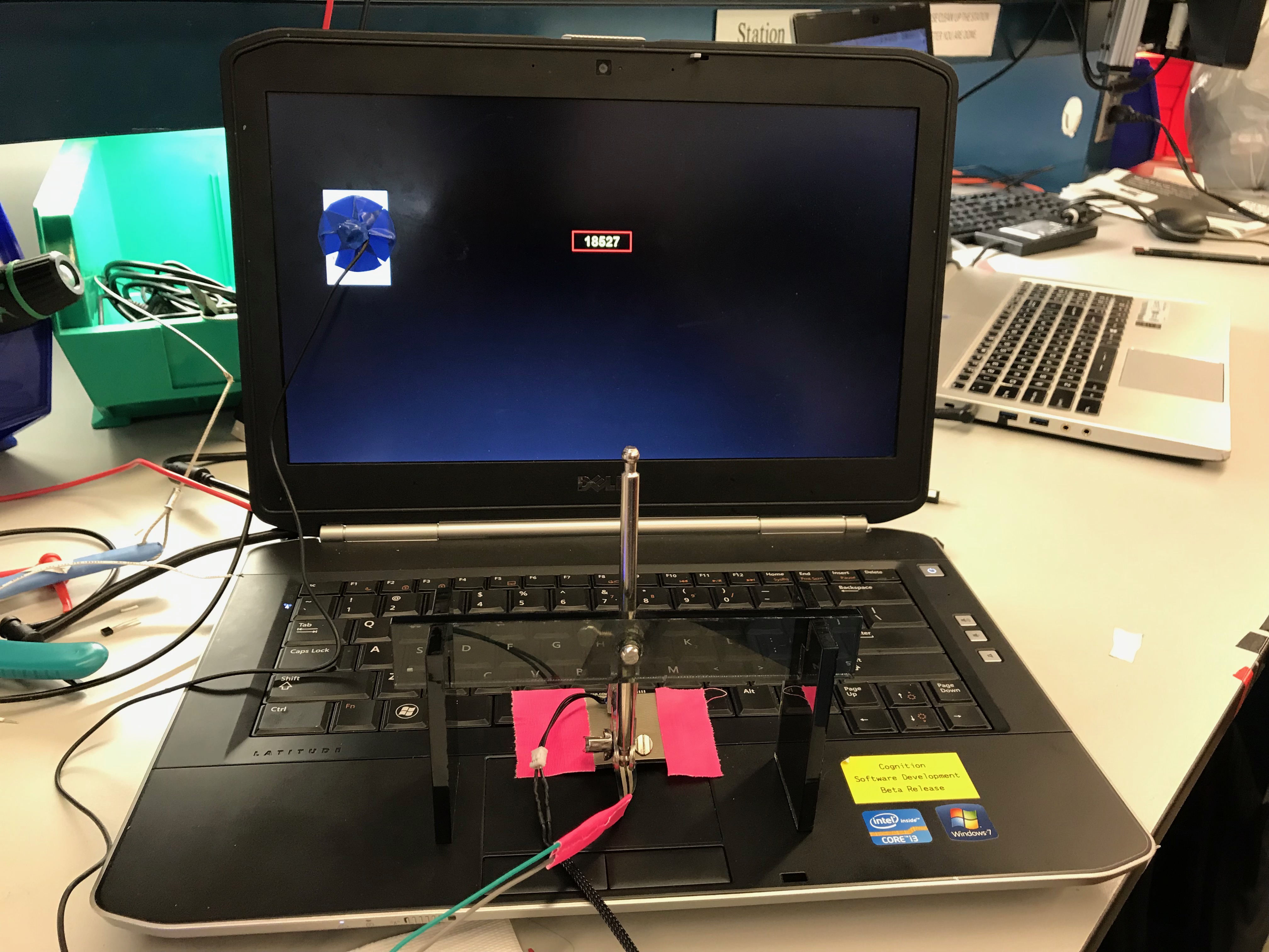
Calibrating computer
-
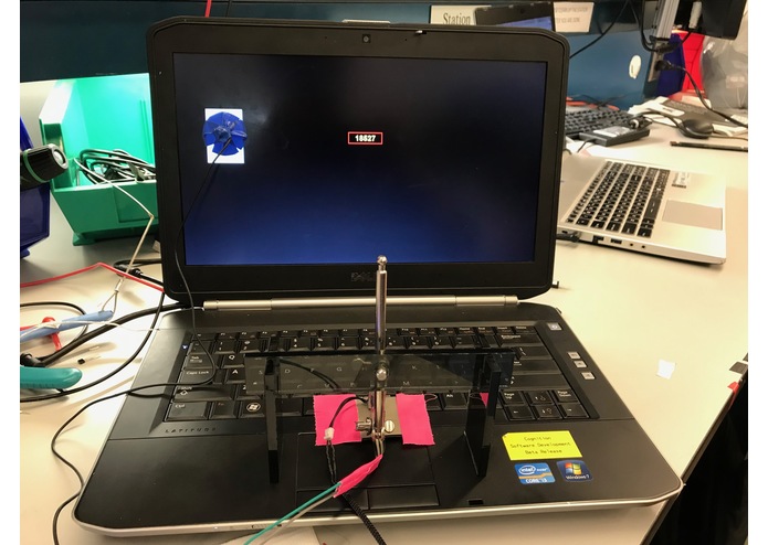
Calibrating computer
-
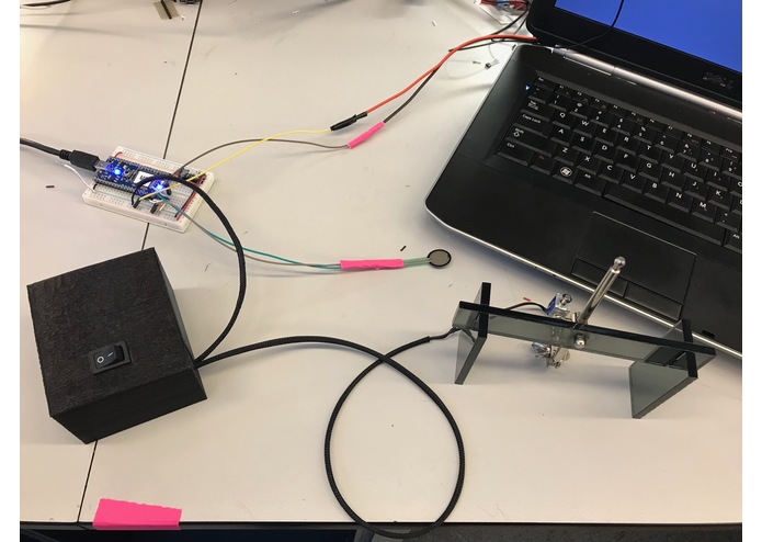
Calibration system
Introduction
Most computers cannot accurately measure highly time-sensitive events due to its inherent latency. We built a way to calculate this latency, enabling regular PCs to be used for sensitive research. In particular, the Psychomotor Vigilance Test, which test a person's reaction time, requires an accuracy of measurement down to a few microseconds using a computer screen and keyboard for stimulation and response respectively.
System Architecture
The test computer displays a stimulus which triggers a light sensor to directly activate a solenoid to press the spacebar. A force sensor is adhered to the spacebar such that it is triggered when the solenoid begins to depress the spacebar. An Mbed is used to measure each time at which the light sensor and force sensor is activated, and saves that information. After many trials to find a data distribution, the difference between what the computer records as the stimulus and response time and what the Mbed records as the stimulus and response time are used as the display and keyboard latency respectively.
Baseline Goal
1) Figure how to build and code a measuring system without a significant latency
2) Being able to find the combined latency of a computer
3) Implement a solenoid for a consistent keyboard depression time
Reach Goal
Being able to find the latency of each part of the computer - OS display, key depression, and OS key detect - individually such that we have a distribution for each part of the system.
Software Effort
1) C code for Mbed sensing, data logging, and communication with computer
2) Clock syncing protocol between Mbed and computer
3) Python for response simulation on computer side
4) Simulating keypress through serial
5) Python for automatically create calculations and graph
Hardware Effort
1) Circuit for light and touch sensor with debouncing, noise filtering, and power control
2) 3D printed box for circuit and batteries
3) Adjustable laser cut stand for solenoid
Prototype and Challenges
Initially, we used a Response Time Box as the minimal latency system that we used to measure our sensors. However, we are unable to see the low level processes of the box as it is running its proprietary software. We switched to Mbed in order to understand and optimize the code for our specific purpose.
We also used the Mbed to control the solenoid after a trigger from the light sensor is registered. We decided that if the solenoid was hardware controlled instead, this would reduce the load on our Mbed and further reduce its latency. In our final iteration, the changing resistance of the light sensor triggers an op-amp comparator that activates a transistor to power the solenoid. The Mbed is only set to detect and log data without controlling anything. We ran into the problem of our components being sub-optimal. The op-amp had a leakage current that would keep the solenoid activated even when light is not being detected. The threshold and output had to be carefully tuned with resistor dividers such that the solenoid is only weakly activated and isn't strong enough to push the key when off.
After prototyping on a breadboard, the sensor circuit was soldered onto a perfboard. The circuit is powered by two 9V batteries that is hardware controlled by an off/on switch. The Mbed is set on a breadboard that is powered by USB from a computer. After the runs are done, the Mbed exports it's files to the computer to be compared.
Baseline and Final Demo
For baseline demo, we had the Response Time box for controlling the solenoid and measuring the sensors. However, using this method, we could only calculate the total latency of the computer and could not know each individual latency since any measurements taken on the Response Time box were relative only to each other and were not in sync with the computer's time measurements. This presents a problem when trying to determine exactly which part of the computer is providing the largest amount of delay.
For final demo, we moved away from using the Response Time box and created our own system using an Mbed. We are able to sync the Mbed with the subject computer so that each event is on the same time scale. We ran into the problem that the program that logs the calibration only logs time relative to the start of the program. We were able to simulate a keypress with the mbed to start the program, thereby finding out exactly when the calibration program's internal timer starts. We were also able to isolate the physical depressing of the keyboard from the OS detection by running a keyboard simulation program from serial. Along with the total system latency, we can now find the display latency, physical key depression latency, and OS keyboard input logging latency with their distributions.
What's next for NASA Response Time Calibration
The next step is to take it further and make it into a polished product

Log in or sign up for Devpost to join the conversation.