What it does
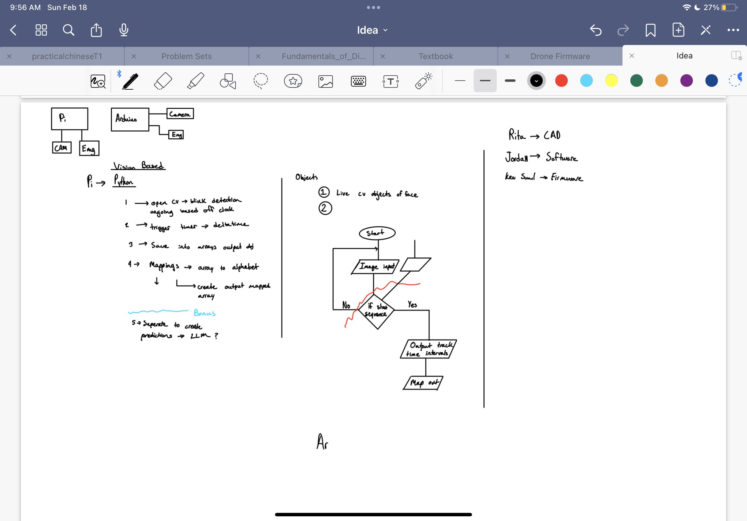
The purpose of this device is to provide an alternative way for those are affected by paraplegia to communicate more effectively. The current solutions are slow and inefficient only producing around 15wpm, with other alternatives becoming increasingly more invasive involving neuro-prosthese implants. Our goal was to offer an cost-effective and efficient solution. This device reads the blinking patterns of the user which will be in morse code, interprets it, and output it as speech. It does this by using computer vision to create a landmark/localization mesh of the user face, then by tracking the eyelid movements it converts the blinks to morse which are then translated using an algorithm and dictionary we created to identity distinct characters and normal blinks.
How we built it
Software
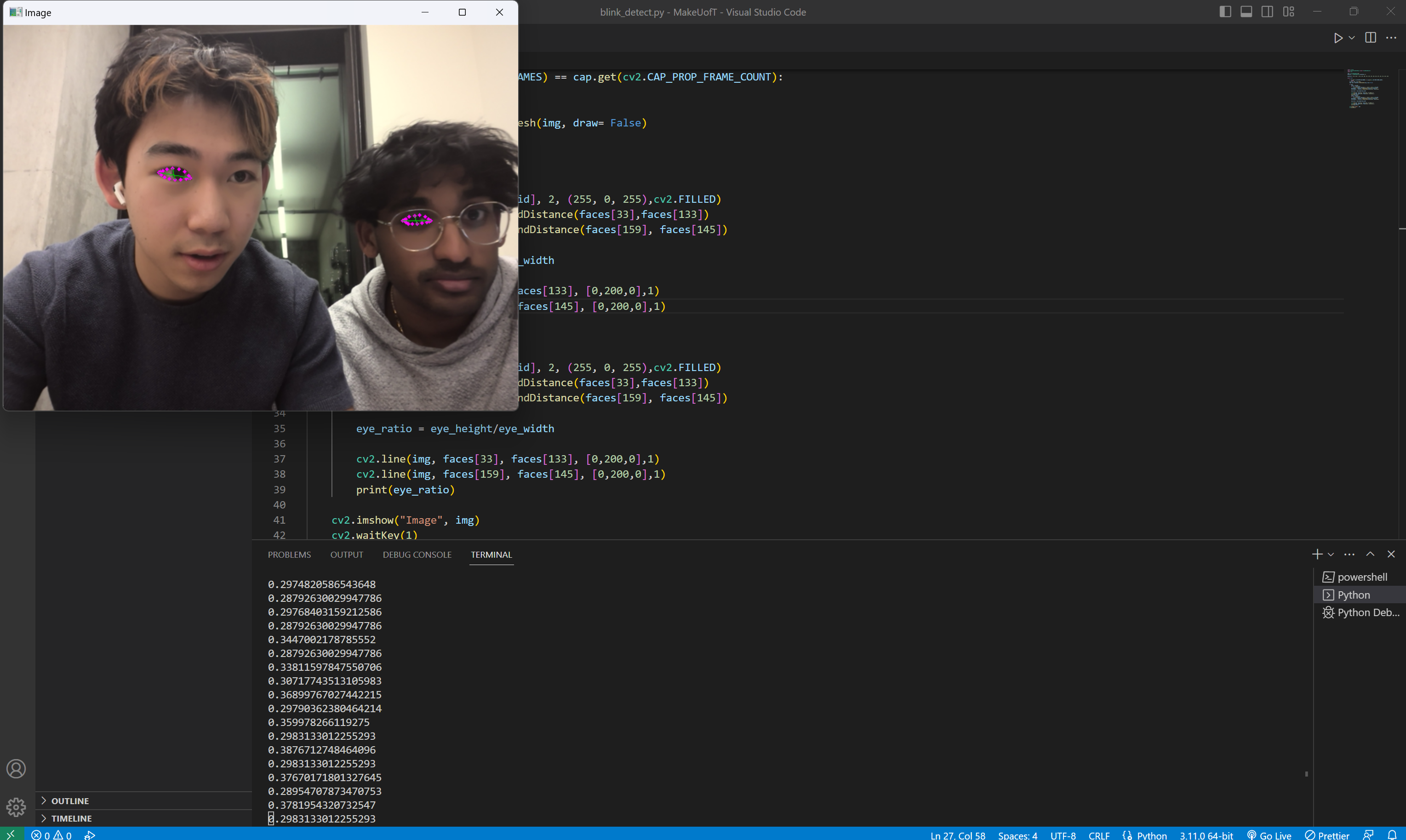
full software can be found here : https://github.com/kjshu-04/morse_link_kshu
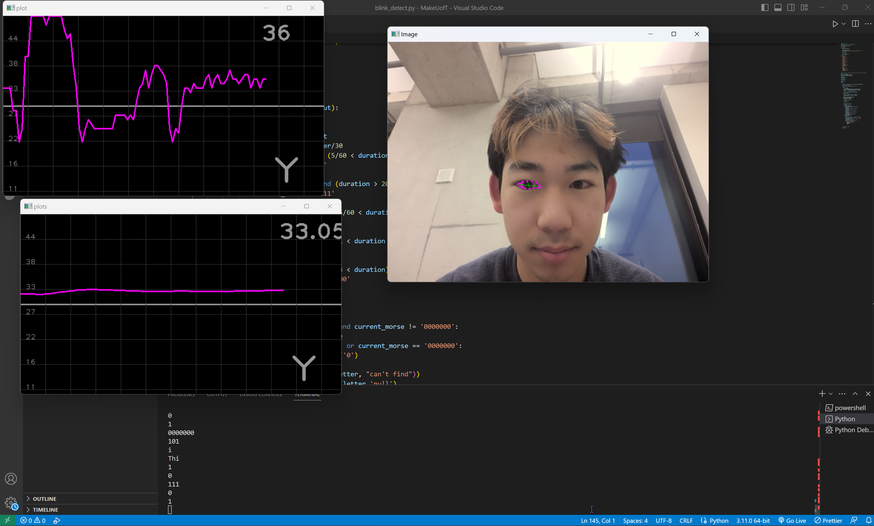
The core of the software components rely on MediaPipe and OpenCV, these provided us with the mesh that we used to localize feature on the user face. The data was inputted through an external webcam for the actual physical device. Then by selecting specific points on this mesh to track, we were able to calculate and track the ratio between the horizontal width and the vertical height of the user eye, this was done to eliminate the error that would occur if the user were to change their distance fromthe camera while the device was operating. Then by tracking differences in this ratio, we were able to determine a valid "blink" threshold through testing, where any ratio below this threshold would be considered a blink.
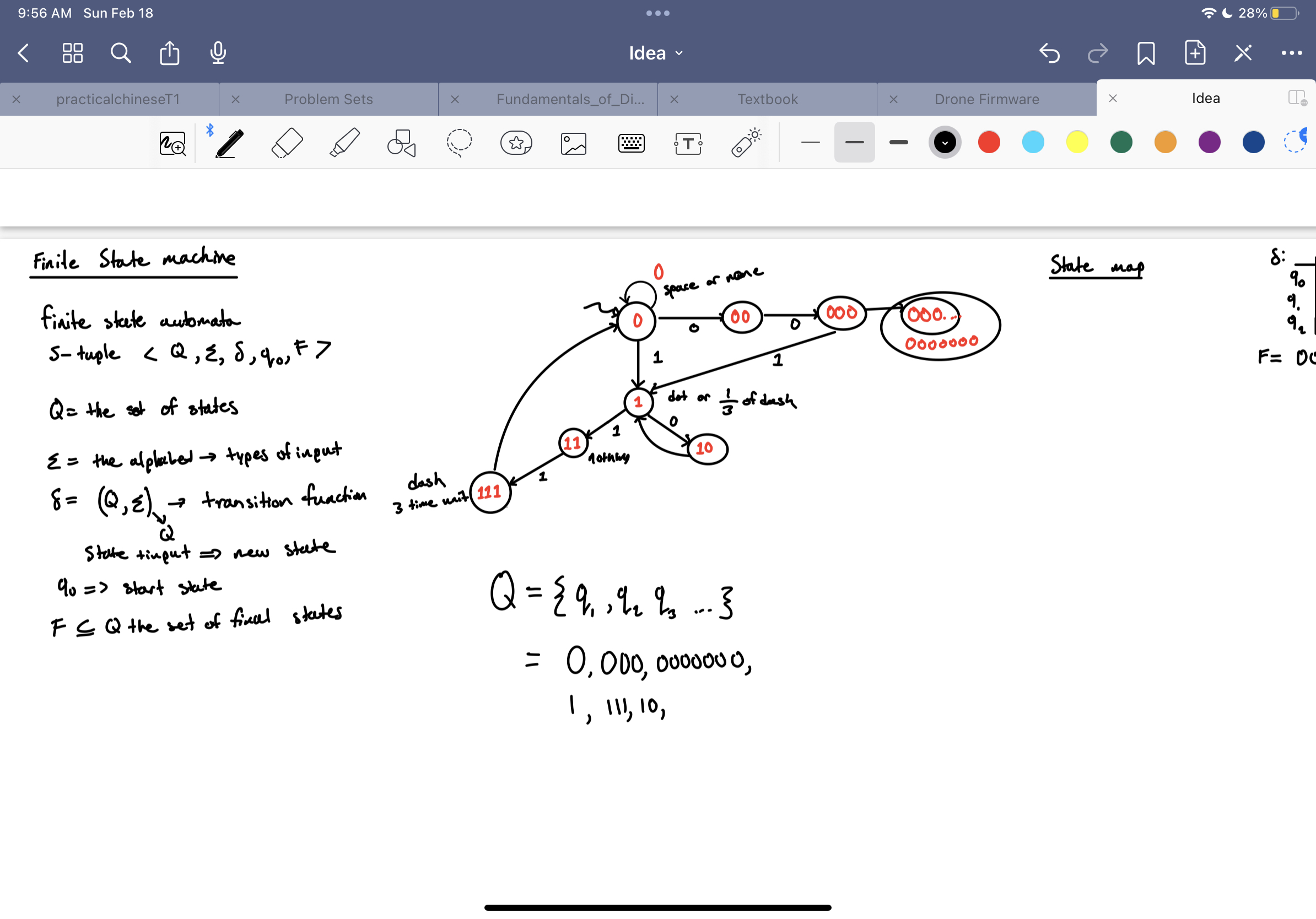
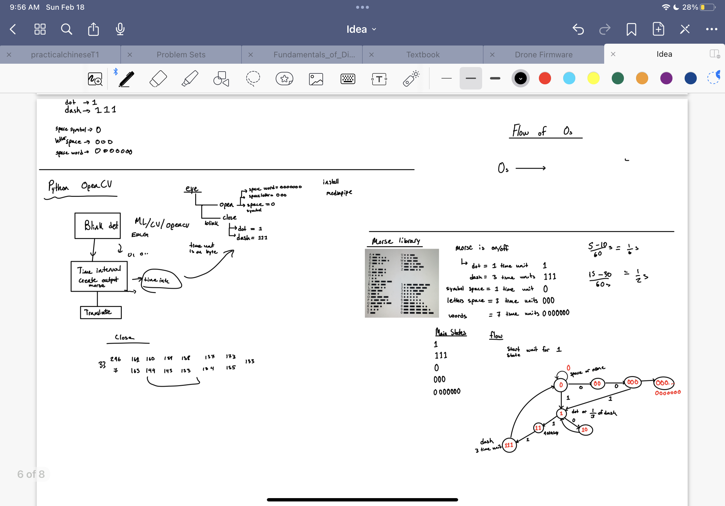
To convert the raw input of the user in morse code, we relied on the properties of the image track library we used. Video was inputted into the code as specific frames, therefore by controlling how frequently we allowed data to be inputted we were able to arrive at a ratio of reading 30 frames every second. By knowing the time interval of each frame, we were then able track when a blink occurred and how long that blink lasted by counting the number of frames that we observed it occur on. Then a simple algorithm to define what each length of blink corresponded to allowed us to convert blink into dashes and dots ( a simple overview below)
        if input_type == 1 and (5/60 < duration < 20/60):
            current_morse = '1'
            print('1')
        elif input_type == 1 and (duration > 20/60):
            current_morse = '111'
            print('111')
        elif input_type == 0 and (5/60 < duration < 1):
            current_morse = '0'
            print('0')
        elif input_type == 0 and (1 < duration < 3):
            current_morse = '000'
            print('000')
        elif input_type == 0 and (3 < duration):
            current_morse = '0000000'
            print('0000000')
Then, all that need was to track when a letter was entered and adding that letter to a word, then adding a library that will output an audio of a string input.
Electrical: The different components used for the electrical part of this project was an Arduino Nano, IR sensor, speaker, and a transistor amplifier. Communication between the components was done through a bread board kit. Speaker amplification modules were not accessible during the competition so a simple NPN transistor amplifier was implemented to increase speaker volume. Input for the Arduino Nano was the third pin on the board, which could be connected with a button, IR sensor, or another output from another board. From the inputs the board would output sounds to the speaker using the PWM function. Use of an IR sensor could detect the presence of a reflective surface such as an eye using the physical properties of diodes. Allowing the detection of blinking without computer vison.
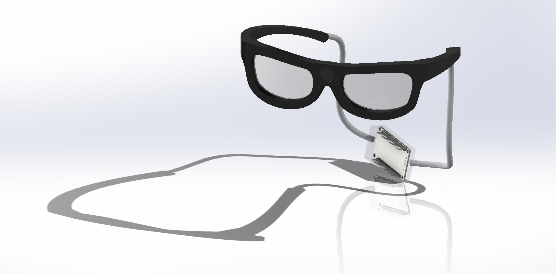
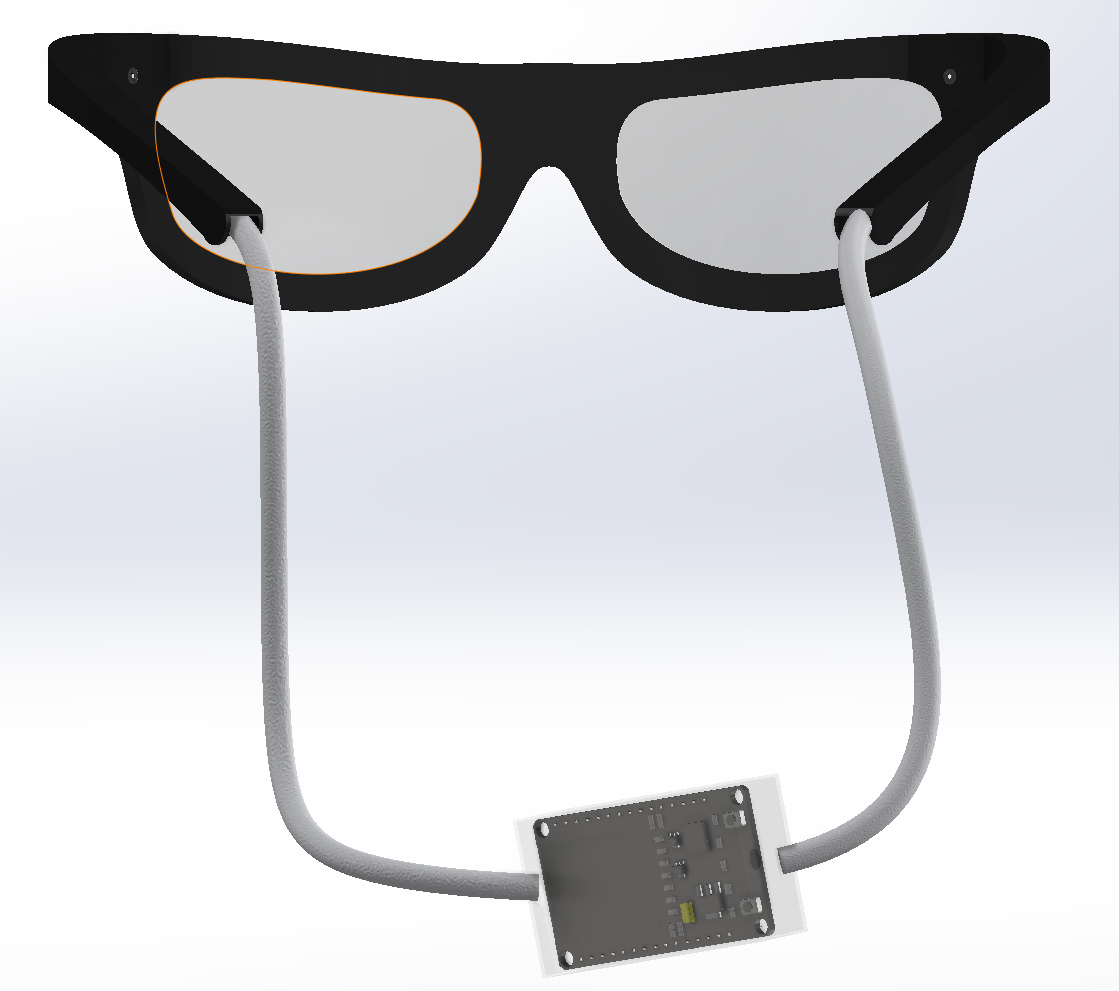
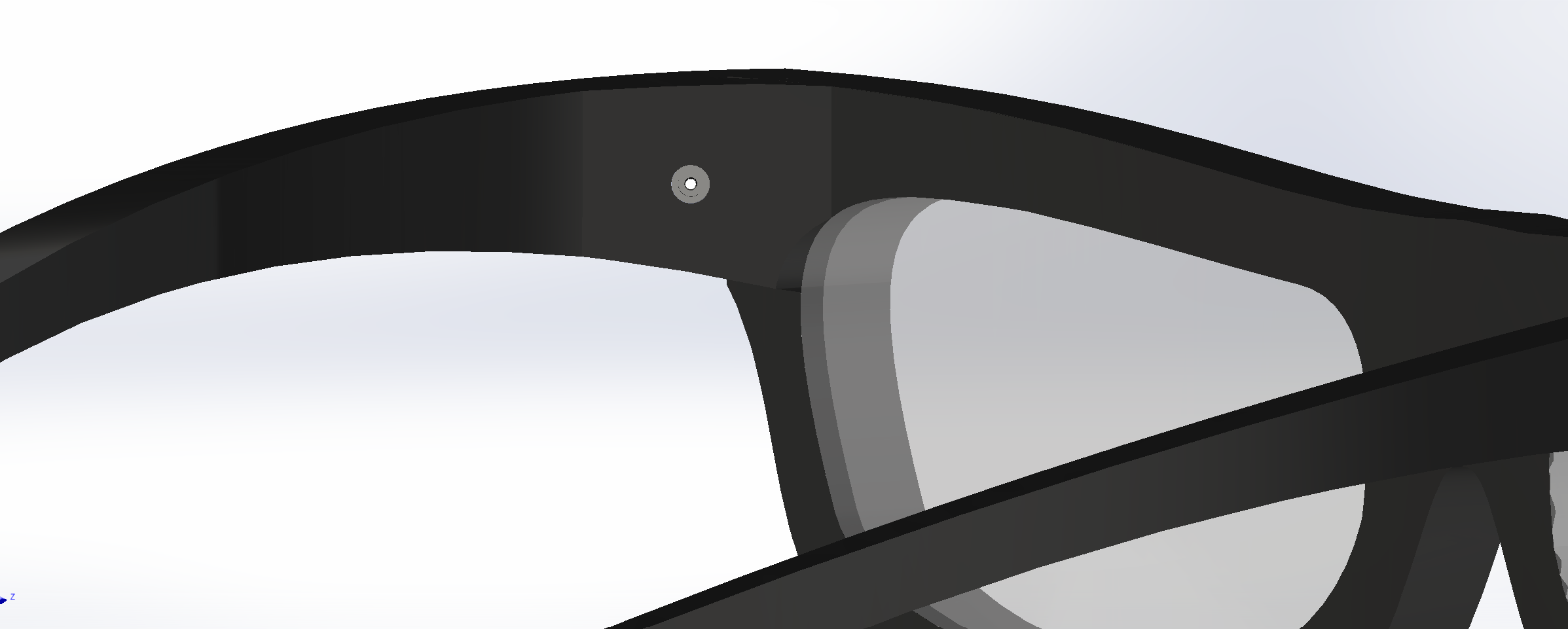
CAD: SOLIDWORKS was used to create the CAD of this design. The overall approach to the design was to ensure that the hardware on the glasses would blend in well with the glasses to produce a sleek design. The frame of the glasses followed a YouTube tutorial (https://www.youtube.com/watch?v=DJumeDiaqVc), modifying the thickness of the glasses to ensure that the wiring would fit within the frame of the glasses. Then, a small speaker was made and mounted in the center of the glasses for the best audio output reach. A small camera was imported from GrabCAD (https://grabcad.com/library/mini-camera-3) and mounted onto the corners of the glasses at an angle so it would be able to capture the eyes. Then, a box which contained the ESP-32 from GrabCAD (https://grabcad.com/library/esp-32-1) was made along with two strings to act as a casing for the wiring.
Challenges we ran into
There were many design iterations that we had to go through in a very short period of time due to the limits of the materials and our skills. Our original plan was to convert the ECG sensor that we were given in our competition package into a EMG sensor that would be able to detect the muscular impuses given off by the user blinking, however, due to a faulty amplification board and lack of replacement parts we had to scrap this idea.
Our next option was to create a Machine Learning Model that would be able to detect blinking. We used Edge Impulse with a labelled dataset that we obtained from RoboFlow to train the model, however we were dissatified with the accuracy and capabilities of the model (see media for data results). Leading to us making the decision to transition to a computer vision approach at around 11 pm.
Overall, the CAD was difficult to make as our experience with SolidWorks has mostly been limited to schoolwork. However, with the use of online resources, it made it manageable.
Accomplishments that we're proud of
- Computer vision able to accurately detect blink and output morse code
- Fully Rendered CAD Design of Ideal product
- Physical design created with limited resources
What we learned
- Computer Vision Blink Detection
- Edge Impluse Machine Learning Training
- Finite State Machines
- Many new Solidworks features
What's next for MorseLink
We hope to continue and refine this project after this hackathon to hopeful create a device similar to our CAD design!!


Log in or sign up for Devpost to join the conversation.