-
-
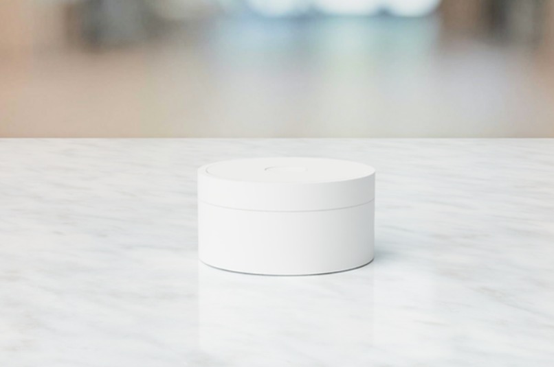
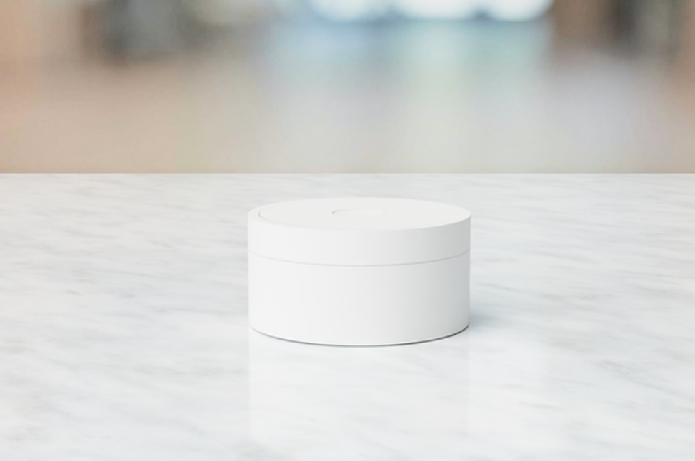
Early Rendering of the Future The Grizzly Product Development
-
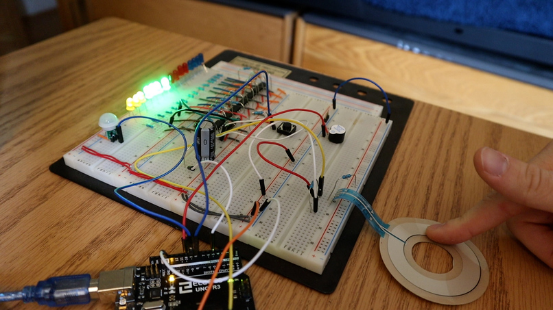
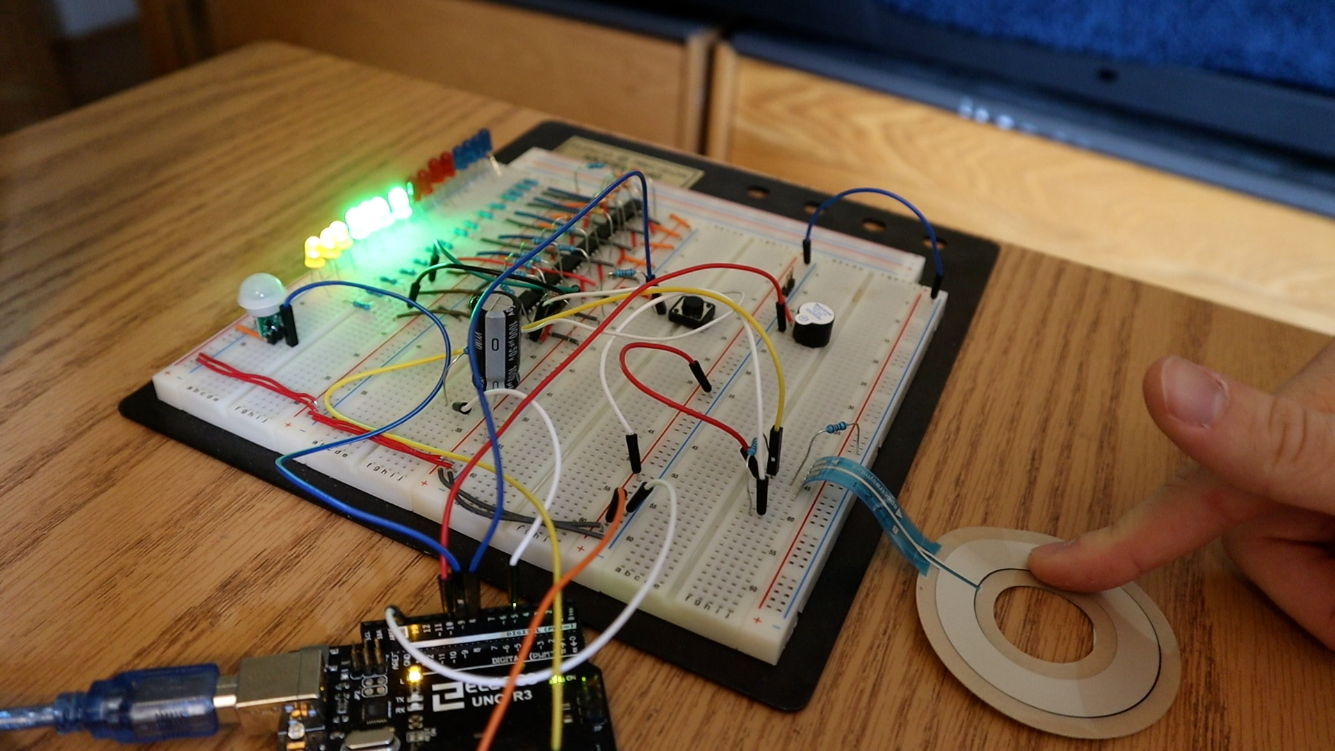
The Grizzly Final Project Put All Together
Inspiration
This project solves many productivity-related problems - helping users become significantly more productive in their everyday work by allowing themselves to reach peak levels of flow and personal productivity in all tasks they choose to do.
The truth is that so many people are wasting hours upon hours of their time on absolutely useless tasks while doing them unproductively. This technology helps solve that problem. The Grizzly allows users to have additional free time because users were able to stay productive by being able to do the tasks that gave them the most value while in a state of flow.
What it does
Designed to give you results, The Grizzly tracks your productivity and gives you data on how much time you are spending doing focused and important work. It does this due to its functional Pomodoro timer design. The Grizzly is designed with an LED ring and a button in the middle: you set the timer by turning on the LEDs and then click the center button to turn it on. Then the timer starts counting down. During this time, the device sends the data to your computer which then logs this data to your corresponding account. In other words, set a short time (e.g. 30 minutes) by bringing your finger in a circle and then allow yourself to work focused and non-stop until the timer is done. Once the work period is done, take a short break (5 minutes) to recharge and repeat. The secret to productivity is not doing more in less time, but doing more of what matters. The Grizzly helps you track this time and then graph/analyze it in the desktop application. This application works by reading the serial data The Grizzly picks up from your computer port then analyzes it accordingly.
That's not all! You can also use the stopwatch mode, which works by pressing the stopwatch whenever you want to record the amount of time you spend doing your most important skill. The goal then is to get this number as high as possible. As a result, it gamifies the entire work process as you are constantly competing against yourself to get the highest number possible. It is also motivating as you can see exactly how much time you spent working on your most important priorities/habits/tasks.
Beat Procrastination. By setting short periods of work and focus, you are effectively beating procrastination. The idea is called 'chunking', where you split a task into smaller bits to motivate you to start. The Grizzly helps you do exactly that.
Become Happier. Research shows that people are happiest when they see results and evidence of progress towards their goals and a purpose in life. On top of that, many other sources prove (take for instance The Happiness Advantage by Shawn Achor or the mountain of resources from the Blue Zones by Dan Buettner) that the happier you are the more productive you will be. It is a win-win situation.
How we built it
Let’s begin with the hardware. The final solution included fifteen comparators with fifteen LEDs all with adjacent current limiting resistors. What’s important to note here is the number of LEDs - decreasing from 24 to 15. This choice was made simply for redundancy purposes: fifteen LEDs results in each LED representing four minutes of time. People typically work in periods of 25 or 40 minutes, thus getting any more specific was not necessary. On top of the comparators, the input signal to said comparators was a low pass filter - allowing the comparators to work as necessary. Because the switching speed of the compators is under 300 nanoseconds (datasheet of LM139). Additionally was the distance sensor: a sensor that gets the device out of sleep mode. When triggered with someone’s hand, the distance sensor displays the time remaining of the timer or a small animation signaling the stopwatch is counting down. This is connected to Pin B1 and triggers the resulting PinB interrupt vector when the distance sensor goes high. Next is the momentary push button, connected to Pin B0 and to the PinB interrupt vector when it goes high. On top of that is the piezo buzzer, which is simply connected to an output pin on the arduino. Finally, is the soft potentiometer, which is connected to an input analog pin, namely A0, on the Atmega32p. As the soft potentiometer changes, so does the ADC value.
Next, let’s analyze the final software solutions to the problem. First was the ADC, which captured the value of the soft potentiometer. When The Grizzly is in standby mode, after a certain ADC value has been pressed by the user for 5 seconds, this ADC value gets captured and the user can press the button to begin the timer countdown. If the user does not press the button for 4 seconds, then a timeout timer gets triggered and The Grizzly goes back to standby mode. Given that the user pressed the button, the timer counts down, solving the problem of productivity, as the user is now queued to begin working on their number priority as long as the timer is counting down. The timer then goes into countdown mode, which is reflected by the idle variable being set to two. The user can press the button, triggering an interrupt that pauses the countdown timer. When the timer counts down to zero, it creates a visual and auditory celebration. Next is the stopwatch mode that gets triggered when the user presses the button given that The Grizzly is in idle mode. The stopwatch counts up until the user presses the button again. In this case, the stopwatch stops, and remains in pause mode. If the user presses the button then the stopwatch gets out of pause mode and if the user presses anywhere on the soft potentiometer, The Grizzly returns back to idle mode. Meanwhile, The Grizzly feeds data to the connected computer via the serial out port, so that a software on the computer can read said data, analyze it, and then package it for consumption. This was the final design of The Grizzly.
Challenges we ran into
The largest challenge I ran into was working with the Neopixel LED Ring. I attempted to write the Neopixel LED library myself - a mistake. Next time, I could have appended the library rather than trying to write it myself. This would have saved me multiple hours of playing with the LEDs and the comparators. On the flip side, the LEDs present a clear advantage. Namely that they can be rearranged in any shape. Compare this to the LED ring that has a set diameter. As a result, when I go about 3D printing the shell for the product, I can place the LEDs directly above the soft potentiometer for ease of mechanical integration. Compare this to the Neopixel LED ring, that is larger than the soft potentiometer - resulting in the LED ring not perfectly corresponding to the diameter of the soft potentiometer. In this regard, we would need some extra 3D printed pieces so that pressing the LED ring directly results in the soft potentiometer being pressed. Compare this to having each individual LED, that can be inserted into a dedicated spot on the top of the 3D printed shell, allowing for less 3D printed shell material as the shell can be created in such a way that the LED gets added directly above the surface of the soft potentiometer. On this note, another related obstacle was the refresh rate of the comparators connected to the low pass filter. This was a challenge, as it took a few seconds for the capacitor to discharge resulting in the comparators appearing to stay “stuck” at one value for those few seconds - creating a UI that appeared to be buggy. This was solved by changing the value of the capacitor, with 100 microFarads being the final choice.
Even after this changed, there was still a problem with the design that made the entire circuit very difficult to work with. This had to do with the soft potentiometer where there was a few second delay when updating the ADC value. In other words, If I was to press on the soft potentiometer and get an ADC value of 800 and then release my finger (the ADC value should now read 0), the ADC value would not jump straight from 800 to zero. Instead, it would take a few seconds to slowly ripple down from 800 to zero. To troubleshoot this problem, I replaced the soft pot with a regular potentiometer. This solved the problem. Therefore, the problem had something to do with the hardware specifications of the soft potentiometer. This was not the only problem faced with the soft potentiometer hardware: the soft potentiometer would oftentimes fluctuate between random numbers even when nobody pressed it. I am not sure if this had to do with how the soft pot was taped to the table or if it had to do with the soft pot materials itself. Regardless, it had to do with the hardware constraint of the soft pot. I managed to solve this by placing a 100k pull down resistor in parallel to the inputted ADC channel. Therefore, changing the hardware to a normal potentiometer would solve the problem. It would, however, bring a new challenge regarding the 3D printed hardware. In this case, we would need some type of mechanical gear system in order to change the value of the potentiometer. This can be done with an adjustable ring on the outside of The Grizzly’s 3D printed hardware. As a result, all of these challenges can be turned into valid next steps for this project.
Accomplishments that we're proud of and What we learned
I am overall very satisfied with this project and with the entire course. When I went about choosing this project, I did my best to think of something that included as many of the courses content as possible. This project does that: containing GPIO, Interrupts, Timers, PWM, ADC, and Serial Communication (I’m only missing some power supplies). Based on this, I very strongly believe that I further reinforced my learning on all key course concepts by going through each one of these topics and then bringing one step further by combining it all together.
What went very well was using the timers and the ADC. I was able to set this up without any challenges. Likely because I spent over eight hours troubleshooting ADC and timer related problems during Lab 4 - the hard work paid off. I am very proud of how I was able to make the PWM to comparator seamless. I had to fundamentally change my approach away from the LED ring, as it was not working regardless of how I sent the data as described in the data sheet. To that end, if I was to use the Neopixel rings in the future, I would have to use the Neopixel Library. This was a challenge, as the PWM did not initially trigger the LEDs. This had to do with the switching frequency of the comparators, resulting in me using a low pass filter to solve the problem (as explained above).
What's next for The Grizzly
The next steps of the process includes the mechanical process of the project which is done by creating a 3D printed shell. This allows the entire project to be packaged up in a user-friendly container. Other than the mechanical improvements, the project can be improved by creating the corresponding computer application that takes in the data, stores it locally on the computer, and then analyzes and presents it to the user. Considering the software and electrical implications, this project can be improved with a different distance sensor or a different cap on the same distance sensor. This sensor would often times get triggered randomly which made it very challenging to work with
A completely new next step can include voice control. Here, the user just tells the timer to stop, pause, or start. This works by utilizing a voice sensor that then sends the data to the computer through the serial port, processes it to uncover language patterns/words through a web API, and then sends it back to The Grizzly to then execute the specified task.

Log in or sign up for Devpost to join the conversation.