-
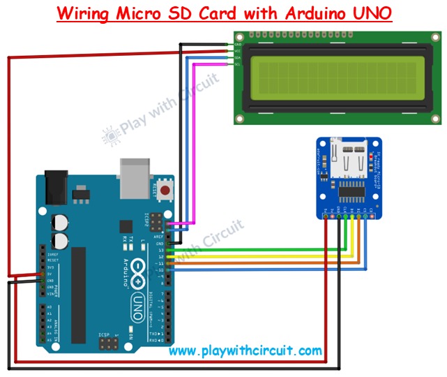
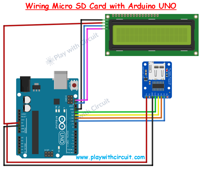
Wiring Diagram
-
Micro SD Card Pinout
-
Micro SD Card Hardware Overview

Imagine you’re working on a weather station that records temperature and humidity every 10 seconds, or a smart irrigation system that logs soil moisture data throughout the day. These kinds of projects quickly generate a large amount of data, far more than the Arduino’s limited built-in memory can store.
So how do you expand storage without upgrading your microcontroller?
The answer is simple: use a Micro SD card. These tiny cards can hold megabytes to gigabytes of data. With the help of a Micro SD card module, you can easily connect one to an Arduino and turn it into a powerful data logger.
In this tutorial, you’ll learn everything you need to know about the Micro SD card module and how to interface it with an Arduino.
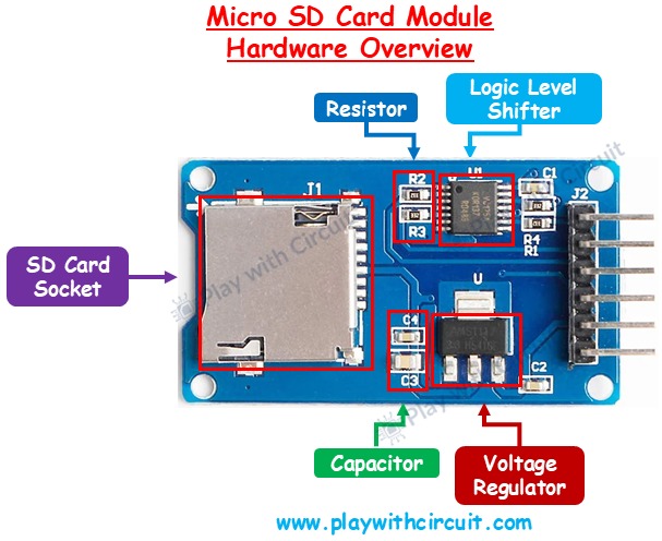
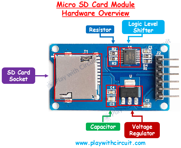
Micro SD Card Module Hardware Overview
A Micro SD card module is designed to safely connect your Arduino to an SD card. It typically includes three major components:
Micro SD Card Socket: This is the slot where you insert the memory card. Most modules have indicators showing the correct orientation so you won’t insert it incorrectly.
3.3V LDO Voltage Regulator: SD cards only work at 3.3V, while an Arduino UNO usually supplies 5V. If you connect 5V directly to the card, it will get damaged. The built-in Low Dropout (LDO) regulator steps down the 5V supply to a steady 3.3V. Even if your input voltage fluctuates slightly, the regulator ensures safe and stable operation.
Logic Level Shifter (74LVC125A chip): Communication between Arduino and the SD card happens via digital signals. Since Arduino UNO uses 5V logic and SD cards use 3.3V logic, a translator is needed. The logic level shifter safely converts 5V signals down to 3.3V before sending them to the card. This prevents damage and ensures smooth communication.
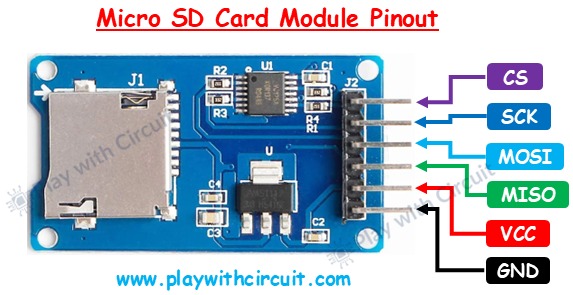
Micro SD Card Module Pinout
The module communicates using the SPI (Serial Peripheral Interface) protocol. Here are the pins:
- GND → Connects to Arduino’s ground.
- VCC → Power supply; connect to Arduino’s 5V pin.
- MISO (Master In Slave Out) → Sends data from the SD card to Arduino.
- MOSI (Master Out Slave In) → Sends data from Arduino to the SD card.
- SCK (Serial Clock) → Provides clock pulses from Arduino to synchronize communication.
- CS (Chip Select) → Tells the SD card when it should be active on the SPI bus.
Interfacing a Micro SD Card Module with Arduino and I2C LCD
Now that you understand the module’s hardware, let’s connect it with an Arduino UNO and an I2C LCD (16×2) to display status information.
The SD card module works using the SPI protocol, so we need to connect its SPI pins to the Arduino’s SPI pins.
Arduino UNO SPI pins mapping:
CS → Pin 10 SCK → Pin 13 MOSI → Pin 11 MISO → Pin 12 VCC → 5V pin GND → GND pin
Connecting the I2C LCD: The I2C LCD uses just two wires (besides power): VCC → 5V GND → GND SCL → A5 (Arduino UNO) SDA → A4 (Arduino UNO)
⚠️ Important: Make sure the A0, A1, A2 address jumpers on the I2C LCD are not shorted. By default, the LCD uses address 0x27. If jumpers are modified, the address may change and the code must be updated accordingly.

Log in or sign up for Devpost to join the conversation.