-
-
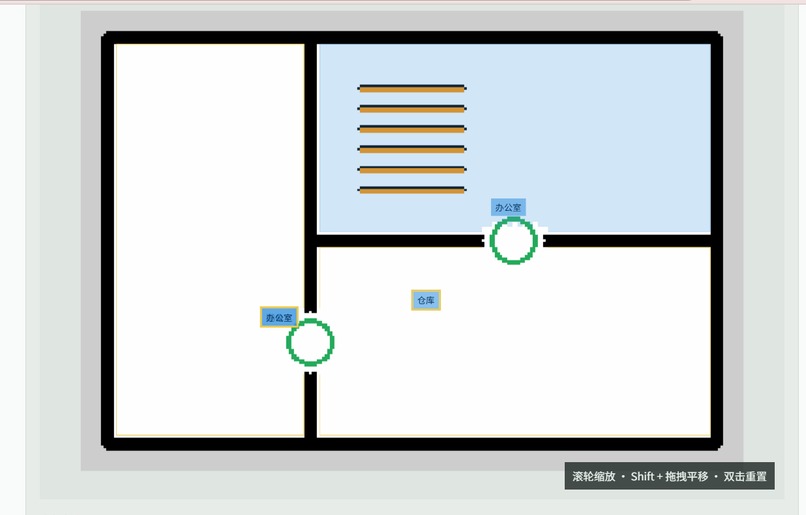
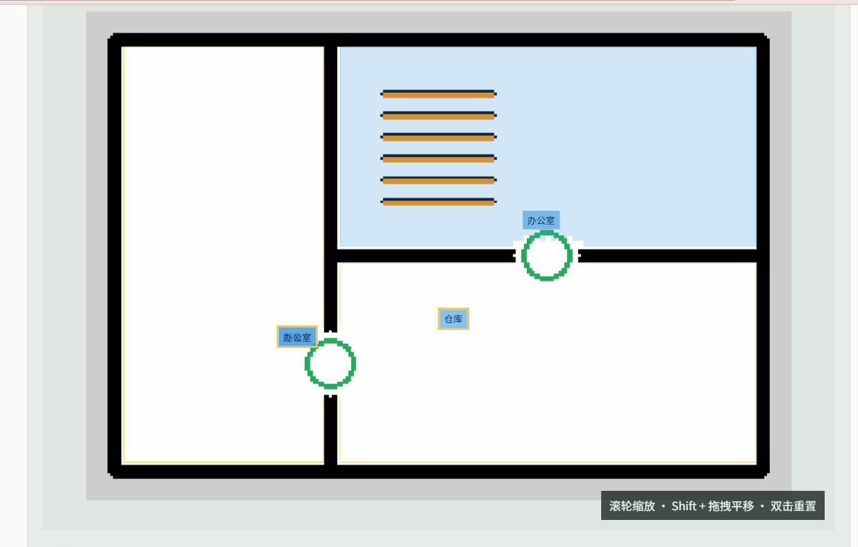
Example 2D maExample 2D map generated from a structured DXF floor plan.p generated from a structured DXF floor plan.
-
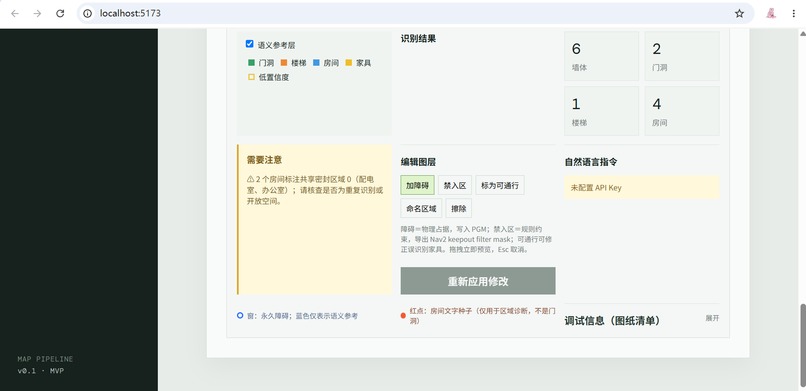
DXF analysis generated by Mapwright, summarizing detected elements, potential issues, and conversion readiness.

Inspiration
When a robot enters a new indoor environment, it needs a map before it can navigate. A common approach is to manually drive the robot around the site and build a map using SLAM. However, many buildings already have architectural drawings that describe their layout.
The problem is that architectural CAD drawings and robot navigation maps use very different representations. A DXF drawing may contain walls, doors, stairs, room names, and other architectural information, while a ROS navigation system usually expects a 2D occupancy grid such as a PGM image with YAML metadata.
We built Mapwright to explore a focused question:
Can an existing structured CAD floor plan be converted into a basic ROS-compatible map without manually redrawing the entire environment?
We deliberately scoped the project to a small, demonstrable 2D conversion pipeline rather than attempting 3D reconstruction, SLAM, simulation, or a complete navigation system.
What it does
Mapwright converts a structured DXF floor plan into a 2D map usable in a ROS mapping workflow, and wraps that pipeline in a browser interface so the result can be reviewed and corrected before export.
The current version can:
- Read a DXF file that follows predefined layer and block conventions
- Extract architectural elements such as walls, doors, stairs, and room labels
- Report detected entities, warnings, and conversion readiness before the map is generated
- Convert the drawing geometry into a 2D occupancy grid
- Export a ROS-compatible PGM map with YAML metadata, plus a PNG preview
- Apply rules based on robot capability profiles:
wheeled_amr,quadruped,wheelchair_accessible, andcustom - Emit additional layers where a profile requires them, such as a quadruped speed mask or a keepout mask
- Preview and manually edit the generated map in the browser before downloading
- Accept natural-language editing commands, gated behind an explicit confirmation step
For example, the same architectural element may need to be treated differently depending on the robot. Stairs are generally obstacles for a wheeled robot, while a quadruped robot may be able to enter the area with additional movement restrictions.
Mapwright does not perform 3D reconstruction, autonomous path planning, SLAM, or automatic interpretation of arbitrary floor-plan images. Its input is a structured DXF file rather than any possible CAD drawing.
How we built it
We built Mapwright in Python and separated the conversion process into several stages.
First, the DXF adapter reads entities from selected CAD layers and converts them into a simpler internal representation. Instead of letting the rest of the program depend directly on DXF entities, we store the relevant geometry and semantic information in this intermediate format.
Next, the semantic and robot-profile logic interprets elements such as walls, doors, and stairs. The profile determines how each area should be represented for a particular type of robot.
Finally, the map backend converts the processed geometry from drawing coordinates into raster map coordinates and generates the occupancy map, YAML metadata, preview image, and any profile-specific mask layers.
Around this pipeline we built a FastAPI service and a Vite frontend. POST /api/convert accepts a DXF upload and a profile name and returns entity inspection data, warnings, a preview URL, and a download URL; the generated artifacts are retrieved as a ZIP. The whole stack runs through Docker Compose with a single command.
Natural-language commands are handled by GPT-5.6. Because model output cannot be trusted blindly, every command is turned into a proposed change that the user must confirm before it is applied. If no API key is provided, only the command box is disabled — conversion and manual editing continue to work normally.
We also included sample inputs, example scripts, robot profiles, and a pytest regression suite so that individual parts of the pipeline could be checked separately.
Challenges we ran into
Understanding CAD structure
A DXF file is not automatically a semantic building model. Its usefulness depends heavily on how the original drawing was created. Different drawings may use different layer names, blocks, units, and conventions.
For this prototype, we defined a limited input convention instead of claiming to support every possible CAD file, and surfaced warnings when a drawing does not match it.
Converting vector geometry into a raster map
Architectural drawings use vector coordinates, while a ROS occupancy map is a pixel grid. We had to handle scaling, map resolution, drawing boundaries, coordinate offsets, and the difference between CAD coordinates and image coordinates.
Small errors in this stage can cause walls to become disconnected or make the exported map appear flipped or incorrectly positioned.
Representing robot capabilities
The same environment is not equally traversable for every robot. Our implementation uses profile-based rules that decide how each semantic element becomes occupancy, restricted space, or a separate mask layer.
Creating accurate stair-region polygons, especially for rotated stairs, remains harder than processing individual lines and is still an area we want to improve.
Making an LLM safe to put in the loop
Natural language is a convenient way to describe a map edit, but an incorrect edit silently corrupts a navigation map. We resolved this by never letting the model write to the map directly: it proposes a structured change, the user reviews it, and only then is it applied. We also made the key optional so the product degrades gracefully instead of breaking without it.
Controlling the scope
Our original discussion included many larger possibilities, including richer semantic maps, simulation, and 3D environments. With a short development period, trying to build all of them would have produced an unfinished demo.
The most important product decision we made was to reduce the scope to one complete workflow:
structured DXF input → interpreted 2D geometry → reviewable ROS PGM and YAML output.
Accomplishments that we are proud of
We completed an end-to-end workflow rather than presenting only a concept. A user can upload a structured DXF drawing in the browser, see what was detected and what looks wrong, choose a robot profile, correct the result, and download real ROS map files.
We also designed the project in a modular way. DXF parsing, the internal representation, semantic processing, robot profiles, map exporting, and the web layer are separated, making it easier to improve one part without rewriting the pipeline.
Most importantly, we learned how to turn a broad robotics idea into a smaller and testable prototype within a limited amount of time.
What we learned
Converting a building drawing into a robot map is not only a file-format conversion problem.
Geometry tells us where a line or shape is located, but semantics tell us what that geometry means. A wall, a glass door, and a stair edge may all appear as lines in a CAD file, but a robot should not necessarily treat them in the same way. And what a given piece of semantics implies is not fixed either — it depends on which robot is asking.
We also learned that reliable input conventions are essential, and that a conversion tool is only useful if a human can inspect and correct what it produced.
What's next for Mapwright
The next technical improvement is more accurate stair-region detection. Instead of approximating stairs from groups of lines or their bounding areas, we want to identify the actual stair polygon, including stairs that are rotated in the drawing.
Other possible next steps include:
- Better validation and error messages for unsupported DXF structures
- Support for more CAD drawing conventions
- Testing the generated maps in a real ROS navigation workflow
- Additional robot capability profiles
- Multi-floor drawings and vertical connectivity
Mapwright is currently an early 2D prototype, but it demonstrates how existing architectural information could become a useful starting point for robot map preparation.
Built With
- ai
- python
- ros2
- semanticmapping
- spatialintelligence
- worldmodel


Log in or sign up for Devpost to join the conversation.