-
-

Custom Board
-

Work Flow
-

RedNode
-

Gauge
-

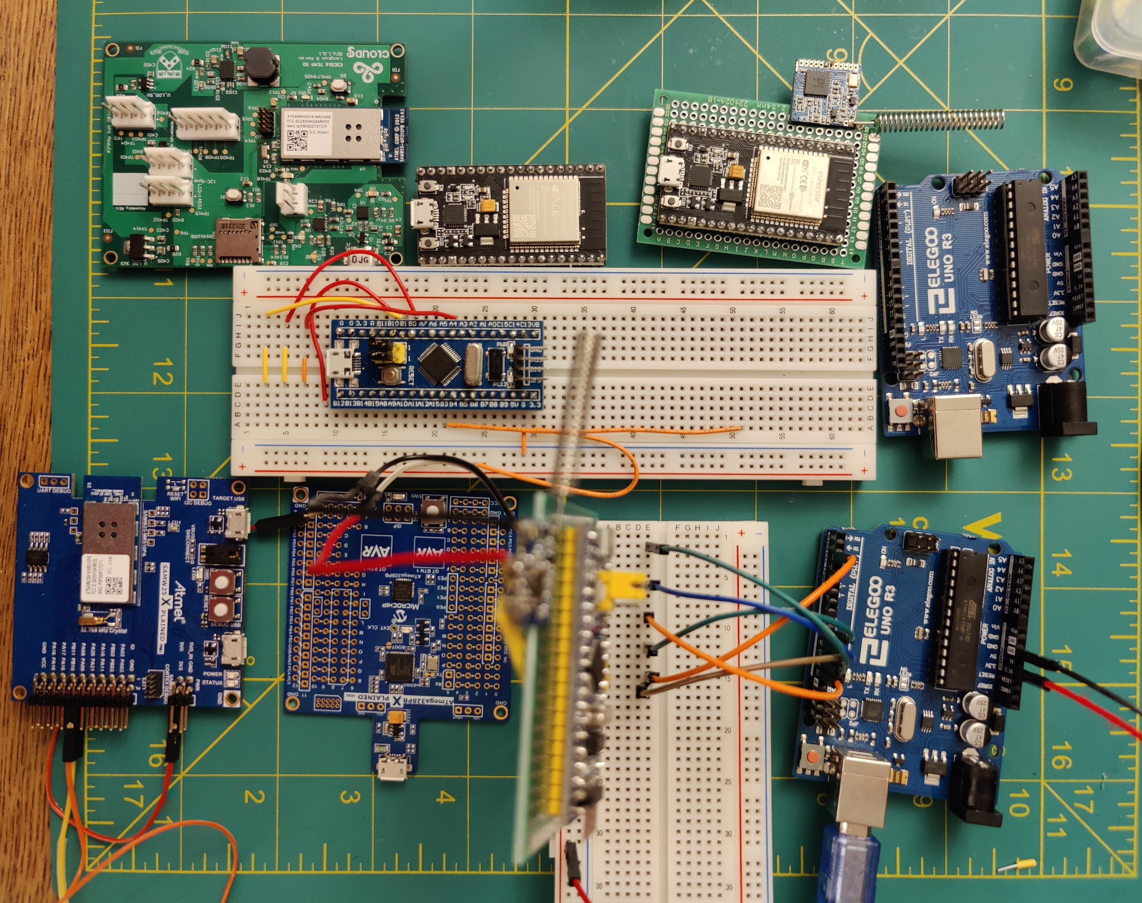
Boards that we used
-

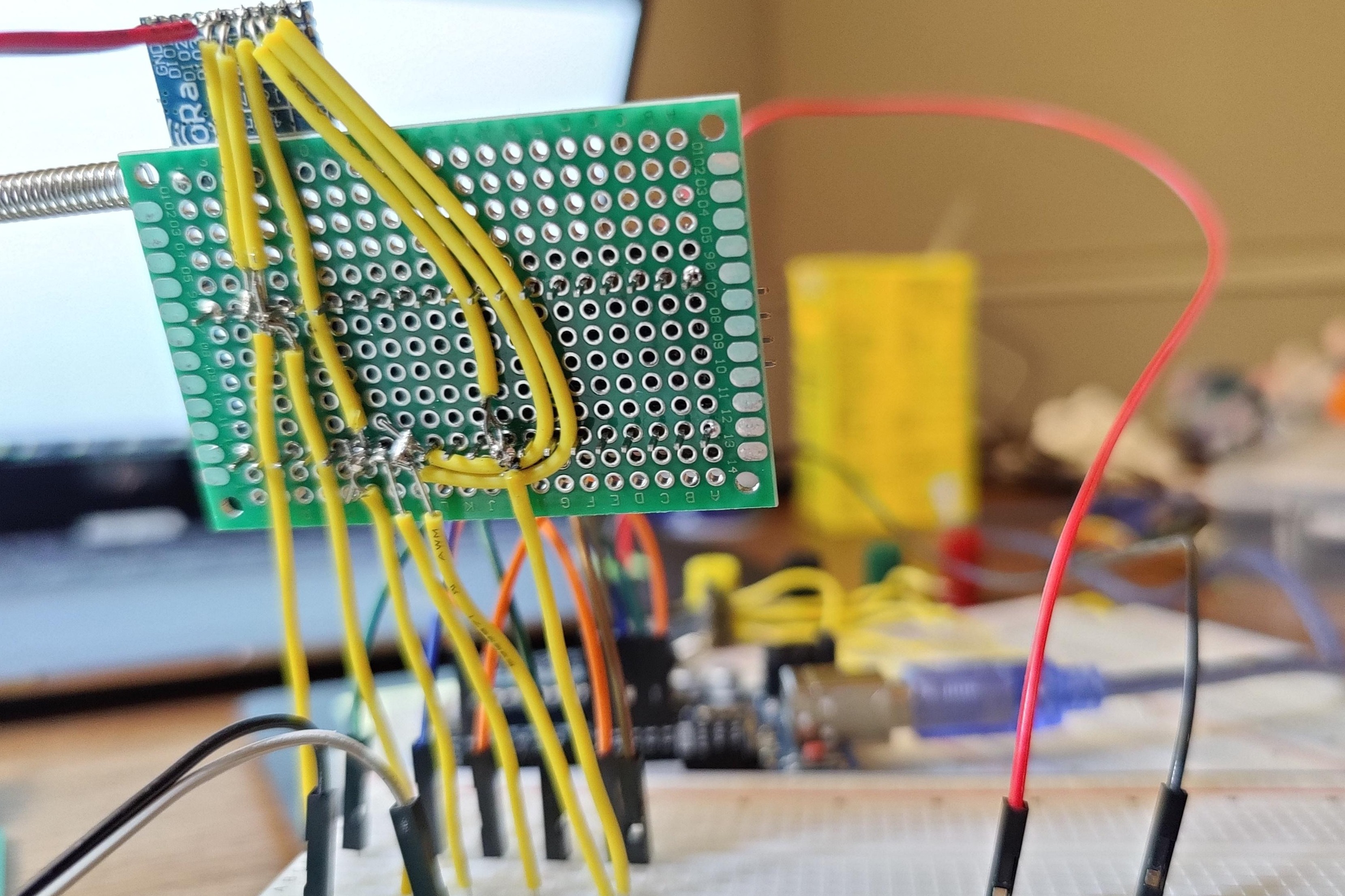
Front of the receiver
-

Back of the receiver
-

ESP32 with Lora soldered in the back
-

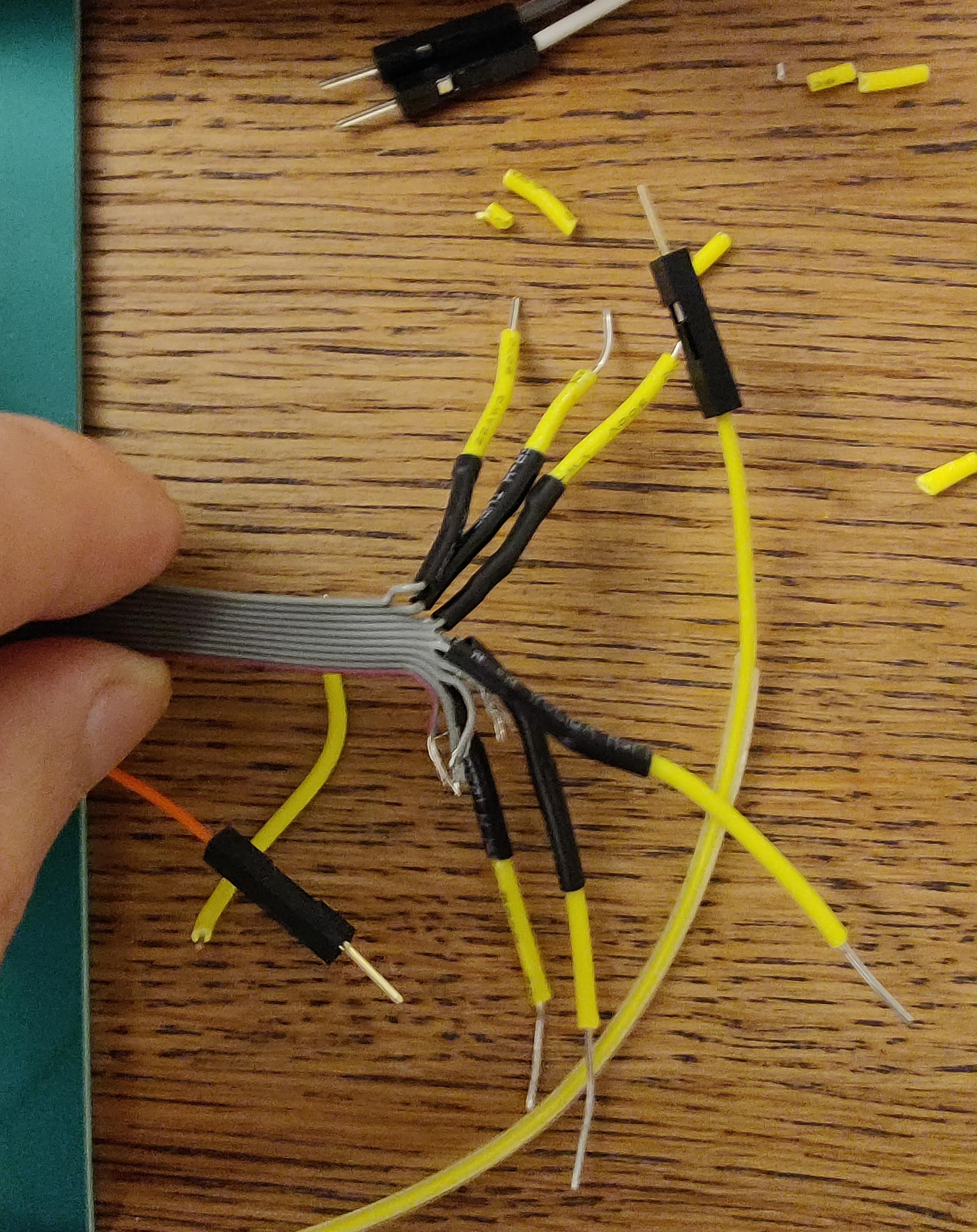
Modified J-Link (but not working very well)


What it Does:
Our devices will collect the data from the humidity sensor and send the data to the receiver via the LoRa module.
Inspiration:
We want to send the data in a long-range via the most efficient and economic way. We did some research and found that LoRa exactly fulfills both long-range and low-power consumption.
How it works:
The sender (ESP32) will send the data collected by the humidity sensor by using the LoRa module. The receiver(Arduino) will receive the data from the LoRa module. With the designed interface, users can monitor the humidity on the screen or on the monitor.
Challenges we ran into:
Since we were using the SAMW25 as the development board, we found it’s hard to implement a driver for the Lora module sx1278. Though we are able to implement SPI, the Lora always remains unconnected. Another issue with our custom board is that, though from Atmel Start we only need to assign 6 pins, the module actually required 8 pins to connect to be fully functional. Since we are lacking the DIO0 (Digital Input pin) and RST (Reset pin) and it’s not possible to connect a jumper to the chip, we decided to use STM32 as the board to achieve the goal. As we modified the driver for STM32 and connected it to the PC, we encountered another issue which was that we didn't have the ST-Link to get it connected, since STM32 required an in-circuit debugger to communicate with the PC as a TTL-USB connection. However, we found a J-Link in the ESE516 LAB kit box, but the pins are fixed for SAMW25 10pins port, so we disassemble the main wire into 10 wires and solder the copper wires with the jumpers with a heat shrink tube to ensure the connections. But since ours is an STM32 development board and it’s not standardized in ‘Connecting J-Link to STM32-Discovery eval boards’ from Segger, we have to guess that for some of the pin connections. As a result, the J-Link is not fully functional with our STM32 board. So, we changed to ESP32 for the last approach. Another issue with our Lora SX1278 is that the pinholes on it are too small to solder, so one of the pin sockets peel apart after the changing wire on that pin.
What we Learned with the prototype:
From this project, we learned how to think thoroughly about an IoT project, since we spend a lot of time on fixing the drivers and the issue of lacking pins of the custom board. As our original goal was the wireless communication tool for outside sports when the user has poor cellar signals, we thought the SX1278 fit our need well, but turns out the main thread of resources for this module is to work with STM32. If we could do more research when we select the modules for our board, these issues might be able to be neglected. However, we did learn about the different implementations on different boards with the same sensor or module on different platforms, because we worked with SAMW25, STM32, ESP32, and Arduino. Though it's a huge pain to switch between each board, and now we can tell why the developer tends to stick with one board for a long time.
What we learned:
From this project, we learned how to implement a project from an idea to a real product. For the hardware layer: We learned to design the PCB board from the schematic to the layout. As we tried different boards, we learned how those boards related to each other and how those default functions are different from each other. By using the logic analyzer, we found how to precise hardware troubleshooting, especially for timing issues with the digital output. For the software layer: we learned several communication protocols like UART SPI and I2C. We also learned how the bootloader works. Before the class, we rarely used the breakpoint in the code, but when we used the SAMW25 on Atmel, I found it's really helpful to locate the issue and monitor the output for debugging. By using the MQTT, we finally knew how the IoT works in real life and how the developer using those tools to develop the device and drain it to get the maximum outcome of the board. We deeply investigated the work function of the LoRa system and now we have a big picture of its work function.
Next Steps:
Since our ST-Link will arrive in a few days, we will continue to test our code on STM32 because STM32 is the MCU that is widely used in the real world. By ensuring the connection between PC and STM32, we could add our GPS module to it to achieve the goal from the start of this semester. Also, STM32 has more mature drivers for this LoRA module and the sensors we chose. We will also test the long range of the data transition in the future. We just tested the system in-door and it works well sometimes while sometimes it does not work well. It might be caused by the unstable soldering of the antenna or the bad pin connections.

Log in or sign up for Devpost to join the conversation.