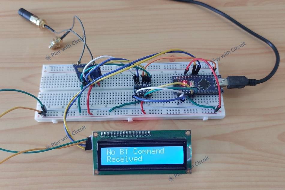
Wireless appliance control is commonly associated with Wi-Fi and internet-connected devices. However, Wi-Fi is not always practical when the two control points are separated by a large distance or when internet connectivity is unavailable.
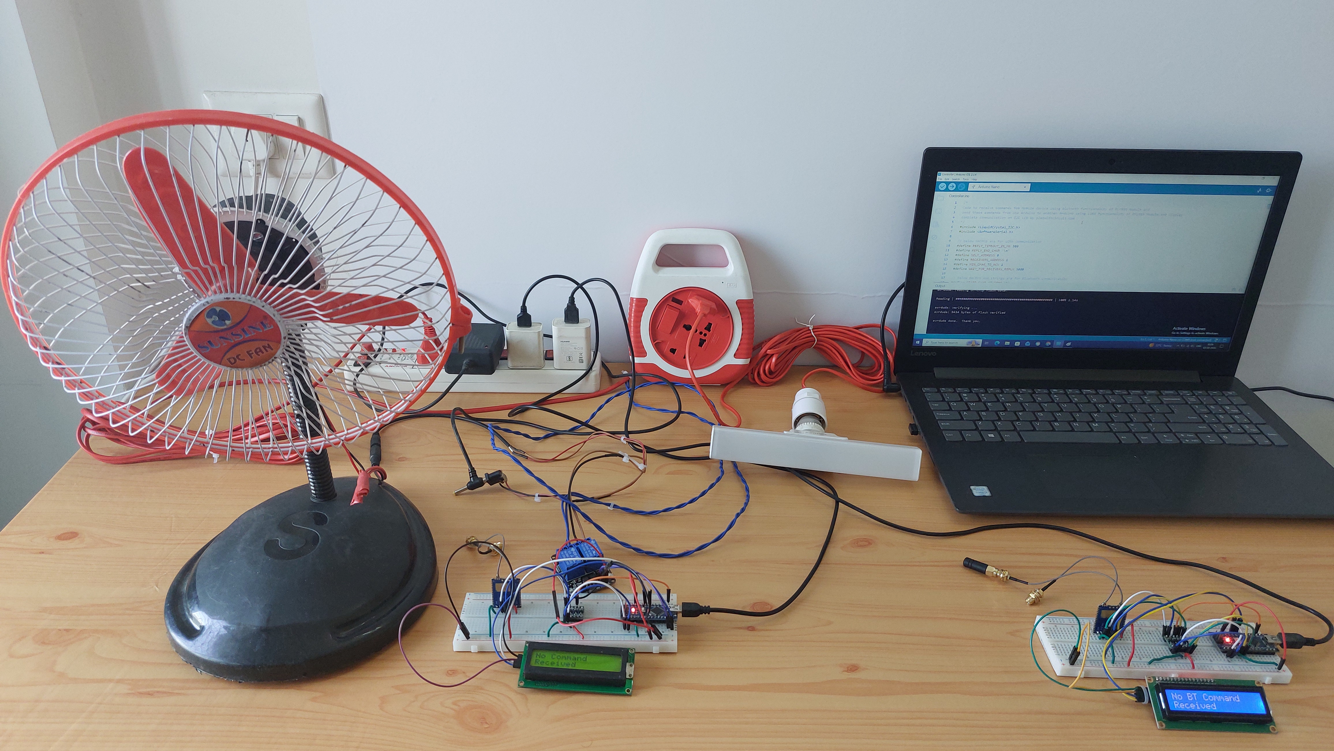
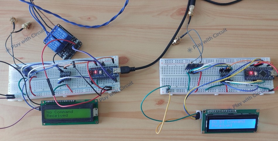
I wanted to build a simple system that demonstrates how BLE and LoRa can work together. BLE provides a convenient interface between a smartphone and the controller, while LoRa handles the long-range communication between the controller and the remote appliance node. The result is a two-node system that can send appliance-control commands over LoRa and operate both AC and DC loads.
What I Built
The project consists of two Arduino-based nodes:
- Controller Node – receives commands from a smartphone through BLE and sends them over LoRa.
- Target Node – receives the LoRa commands and controls the connected appliances through a relay module.
The controller uses a RYLR999 module with both BLE and LoRa communication, while the target node uses another RYLR999 module for LoRa communication.
The target node controls:
- A 240V AC bulb
- A 12V DC fan
A 16×2 I2C LCD is also used at each node to display system information and status.
How the System Works
The overall communication path is:
Smartphone → BLE → Controller Arduino → RYLR999 LoRa → Target RYLR999 → Target Arduino → Relay → Appliance
When a user sends a command from the smartphone, the controller Arduino receives it through BLE. The command is processed and transmitted through the RYLR999 LoRa interface.
The remote RYLR999 receives the message and passes it to the target Arduino. The Arduino then switches the appropriate relay channel.
After processing the command, the target node can send an acknowledgment such as DONE back to the controller through LoRa.
Why BLE + LoRa?
The two wireless technologies have different roles in the project.
Bluetooth Low Energy
BLE provides the local smartphone interface. A smartphone can connect to the RYLR999 BLE interface using a BLE application such as LightBlue.
BLE is useful here because it avoids the need for a dedicated mobile application or internet connection.
LoRa
LoRa is used for communication between the two Arduino nodes.
It is designed for long-range, low-power wireless communication, making it suitable for applications where the controller and target device are separated by a significant distance.
The actual communication range depends on factors such as antenna, placement, height, obstacles, interference, and radio settings.
Hardware Required
- Arduino Nano ×2
- Reyax RYLR999 LoRa + BLE module ×2
- 5V bidirectional voltage level shifter ×2
- 16×2 I2C LCD ×2
- 2-channel relay module
- 12V DC fan
- 240V AC bulb
- 12V power supply
- Jumper wires
- Android smartphone
- LightBlue BLE application
Software
The project can be developed using:
- Arduino IDE 2.3.4 or above
- LiquidCrystal_I2C library by Frank de Brabander, version 1.1.2
- LightBlue BLE application for smartphone communication
RYLR999 Pin Overview
The RYLR999 module provides separate UART connections for BLE and LoRa.
The relevant pins are:
- VDD – power supply
- RST – reset input; pulling it LOW resets the module
- TXD_BLE – BLE UART transmit
- RXD_LoRa – LoRa UART receive
- TXD_LoRa – LoRa UART transmit
- RXD_BLE – BLE UART receive
- GND – ground
The RYLR999 operates with 3.3V logic, while the Arduino Nano uses 5V logic. Therefore, bidirectional voltage level shifters are used between the Arduino and RYLR999 UART signals.
Controller Node Connections
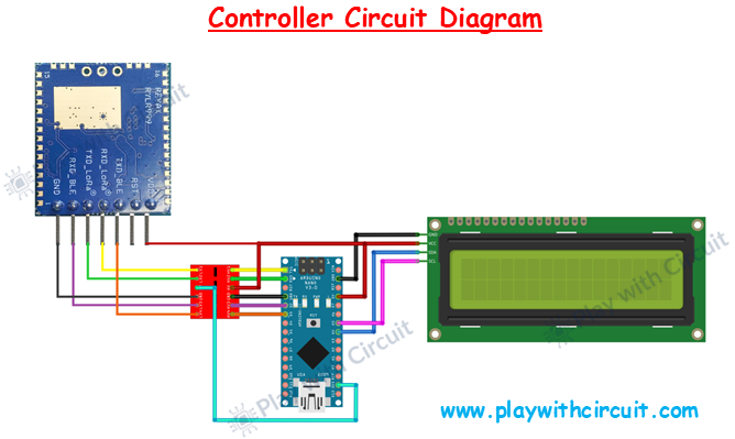
The controller node contains an Arduino Nano, RYLR999, voltage level shifter, and 16×2 I2C LCD.
The RYLR999 power connections are:
- RYLR999 VDD → Arduino 5V
- RYLR999 GND → Arduino GND
The LoRa UART connection uses the voltage level shifter:
- RYLR999 TXD_LoRa → LV2 → HV2 → Arduino RX D0
- Arduino TX D1 → HV1 → LV1 → RYLR999 RXD_LoRa
Since the Arduino Nano has only one hardware serial port, SoftwareSerial is used for the BLE communication.
The BLE connections are:
- Arduino D2 (BLE_TX) → HV3 → LV3 → RYLR999 RXD_BLE
- RYLR999 TXD_BLE → LV4 → HV4 → Arduino D3 (BLE_RX)
For the voltage level shifter:
- HV supply → Arduino 5V
- LV supply → Arduino 3.3V
Controller LCD
The 16×2 I2C LCD is connected as follows:
- LCD VCC → Arduino 5V
- LCD GND → Arduino GND
- LCD SDA → Arduino A4
- LCD SCL → Arduino A5
The LCD uses I2C address 0x27.
Make sure the A0, A1, and A2 address jumpers are not shorted.
Target Node Connections
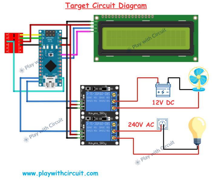
The target node uses another Arduino Nano and RYLR999 module for receiving commands from the controller.
The LoRa UART connection is arranged using the bidirectional voltage level shifter in the same way as the controller's LoRa interface.
The target node does not require the BLE connection because it only needs to communicate with the controller through LoRa.
The target Arduino uses two digital pins to control the relay module:
- Arduino D11 → Relay CH1
- Arduino D12 → Relay CH2
The relay module is powered using:
- Relay VCC → Arduino 5V
- Relay GND → Arduino GND
The target LCD uses the same I2C connections:
- VCC → 5V
- GND → GND
- SDA → A4
- SCL → A5
The I2C address is 0x27, with the A0/A1/A2 address jumpers left unshorted.
Appliance Connections
The first relay channel controls the 240V AC bulb.
The AC live wire is routed through the relay:
AC Live → Relay COM → Relay NO → Bulb
The relay therefore acts as an electrically controlled switch for the bulb.
The second relay channel controls the 12V DC fan.
The relay is connected in series with the 12V fan power supply so that the Arduino can switch the fan ON or OFF.
Command Protocol
The smartphone sends simple application-level commands to the controller through BLE.
The available commands are:
*L1#  → Bulb ON
*L0#  → Bulb OFF
*F1#  → Fan ON
*F0#  → Fan OFF
At the target application level, these correspond to:
L1 → DONE
L0 → DONE
F1 → DONE
F0 → DONE
The DONE response represents an acknowledgment from the target node after processing the command.
The actual RYLR999 LoRa transmission uses its AT-command format, which includes additional protocol information such as the destination address and payload length. The commands shown above represent the application-level commands, not the complete RYLR999 AT command syntax.
Example Command Flow
Suppose the user wants to turn ON the bulb.
The sequence is:
- The user sends
*L1#from the smartphone. - The controller receives the command through BLE.
- The controller processes the command.
- The controller sends the corresponding LoRa message.
- The target RYLR999 receives the message.
- The target Arduino identifies the bulb ON command.
- Relay CH1 is activated.
- The 240V AC bulb turns ON.
- The target node sends an acknowledgment back through LoRa.
The same basic process is used for the fan.
What is Happening Electrically?
There are several communication and electrical interfaces working together.
The smartphone communicates wirelessly with the controller through BLE. The controller Arduino communicates with the RYLR999 using UART.
Because the Arduino and RYLR999 use different logic-voltage levels, the UART signals pass through a bidirectional level shifter.
The controller RYLR999 then transmits the command over LoRa.
At the remote end, the second RYLR999 receives the LoRa data and passes it to the target Arduino. The Arduino interprets the command and changes the state of the corresponding relay.
The relay provides electrical isolation between the Arduino control circuitry and the appliance switching circuit, subject to the relay module's specifications and proper wiring.
Feedback and Acknowledgment
Communication is not limited to sending commands in one direction.
After receiving and processing a command, the target node can send an acknowledgment back to the controller. For example:
L1 → DONE
This creates a basic two-way communication path:
Controller → Target → Controller
One limitation is that the LightBlue BLE application used in this project does not provide a custom interface for displaying the system responses, so the controller does not send these responses back to the smartphone application as a user-facing status message.
STEM and Engineering Concepts
This project combines several practical electronics concepts:
- UART serial communication
- Bluetooth Low Energy
- LoRa wireless communication
- Logic-level voltage conversion
- I2C communication
- Microcontroller-based control
- Relay switching
- AC and DC load control
- Wireless command and acknowledgment
- Embedded-system architecture
It is also a useful example of how different communication technologies can be combined rather than using one wireless technology for every part of a system.
Testing the Project
Testing can be performed in stages rather than connecting everything at once.
Step 1: Test the LCD
Verify that both I2C LCDs initialize correctly and display the expected information.
If the display does not respond, check the I2C address and wiring. The expected address in this setup is 0x27.
Step 2: Test BLE
Connect the smartphone to the controller RYLR999 through the LightBlue application and verify that commands are being received by the Arduino.
Step 3: Test LoRa Communication
Test communication between the two RYLR999 modules before connecting the appliances.
Verify that commands transmitted by the controller reach the target node correctly.
Step 4: Test the Relays
Connect the relay module to the target Arduino and verify that:
- D11 controls relay CH1.
- D12 controls relay CH2.
Step 5: Test the Complete System
Once the individual sections work correctly, combine them and test the complete communication path:
Smartphone → BLE → Controller → LoRa → Target → Relay → Appliance
Challenges
One of the main challenges is handling the different communication interfaces in the system.
The Arduino Nano has a single hardware UART, while the RYLR999 provides separate BLE and LoRa UART interfaces. SoftwareSerial is therefore used for BLE communication.
Another important consideration is the difference between the Arduino's 5V logic and the RYLR999's 3.3V logic. The bidirectional level shifters are necessary to interface the UART signals correctly.
The project also combines low-voltage electronics with a 240V AC load, which requires careful attention to electrical safety.
What I Learned
This project helped demonstrate how BLE and LoRa can be combined to create a practical wireless control system.
It also provides hands-on experience with:
- UART communication
- SoftwareSerial
- BLE interfaces
- LoRa communication
- Logic-level conversion
- I2C displays
- Relay control
- Two-way wireless communication
Most importantly, the project shows that a smartphone-controlled system does not necessarily need Wi-Fi or cloud connectivity.
Applications
The same architecture can be adapted for different applications, including:
- Remote appliance switching
- Farm and agricultural equipment
- Industrial control interfaces
- Remote lighting systems
- Pump control
- Building automation
- Long-range sensor and actuator systems
- Remote machinery control
The exact application depends on the required range, load type, environmental conditions, and safety requirements.
Limitations and Future Improvements
The current project is intended as a practical demonstration of BLE-to-LoRa appliance control.
Possible future improvements include:
- Adding a custom smartphone application
- Displaying acknowledgment messages directly in the mobile interface
- Adding more relay channels
- Adding sensors for monitoring
- Adding stronger error handling and retransmission logic
- Recording communication status
- Adding authentication for command access
- Designing a dedicated PCB
- Adding enclosure and electrical protection
- Integrating additional automation rules
Safety
The project includes a 240V AC bulb, so the mains section must be treated as hazardous.
Always disconnect mains power before making or changing AC connections. Use properly rated relays, wires, connectors, insulation, and protection components.
If you are not experienced with mains wiring, have the AC portion installed or checked by a qualified electrician.
The Arduino, RYLR999, and other low-voltage electronics should be kept physically and electrically separated from exposed mains connections.
Project Resources
The complete project documentation, including the detailed circuit connections and implementation information, is available in the original Play with Circuit tutorial.
You can use the full tutorial as a reference when building the controller and target nodes.
Conclusion
This project demonstrates a simple but useful wireless architecture for controlling appliances over a long distance.
Instead of using Wi-Fi or an internet connection, BLE provides the smartphone interface while LoRa provides communication between the two Arduino nodes.
The combination of Arduino Nano, RYLR999, bidirectional level shifting, I2C LCDs, and relay control creates a practical platform that can be extended to many other long-range automation and control applications.
The project also highlights an important embedded-systems principle: different communication technologies can be combined so that each one handles the part of the system it is best suited for.

Log in or sign up for Devpost to join the conversation.