-
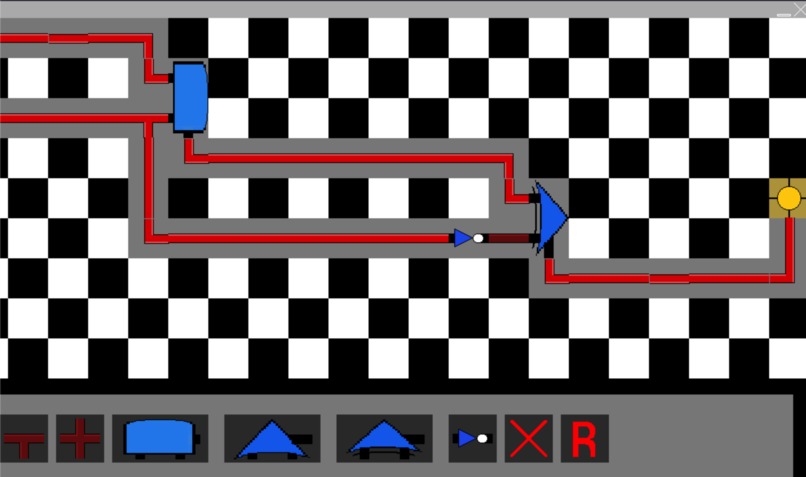
Example of a circuit

Inspiration
This project was inspired by our passion for computer architecture. While we know from experience that learning computer architecture is difficult, we were inspired to make learning computer architecture as accessible and intuitive as possible to any student.
What it does
The "circuit simulator" allows users to create complex circuits using various logic gates, such as AND, OR, XOR, and NOT gate, along with wires connected to power sources. This allows visualize the mechanisms behind circuits using these logic gates, which are the foundation to computer architecture. Check the GitHub repository to see what each logic gate looks like!
How we built it
We build this simulation using Python and specifically pygame to handle the creation of the window, game objects, and rendering of the simulation. This project was specifically created in an online editor called Replit, which automatically hosts the simulation for anyone to readily run.
Challenges we ran into
Originally, the simulation was going to include various tutorials and challenges to the user to build certain circuits, which could be tested for correctness and the simulation could offer tips to complete the circuit. Due to time constraints, it was not able to be implemented on time.
Accomplishments that we're proud of
The simulation was built which runs very smoothly and can handle the logic of power input and outputs along with the combination of gates through the algorithm we implemented to run power through wires, and check input wires when connected to the logic gates.
What we learned
We learned a lot about algorithm design to implement the ability for power to correctly flow through the wires and gates in the correct direction. Additionally, we developed a deeper understanding of computer architecture.
What's next for Logic Gate Simulator
We are likely to implement the tutorials and challenges we initially wanted to include in the simulation. Such challenges include building and XOR gate from scratch, building an arithmetic adder, and creating a MUX circuit.

Log in or sign up for Devpost to join the conversation.