-
-

LockSafe from Above
-

LockSafe from Below
-

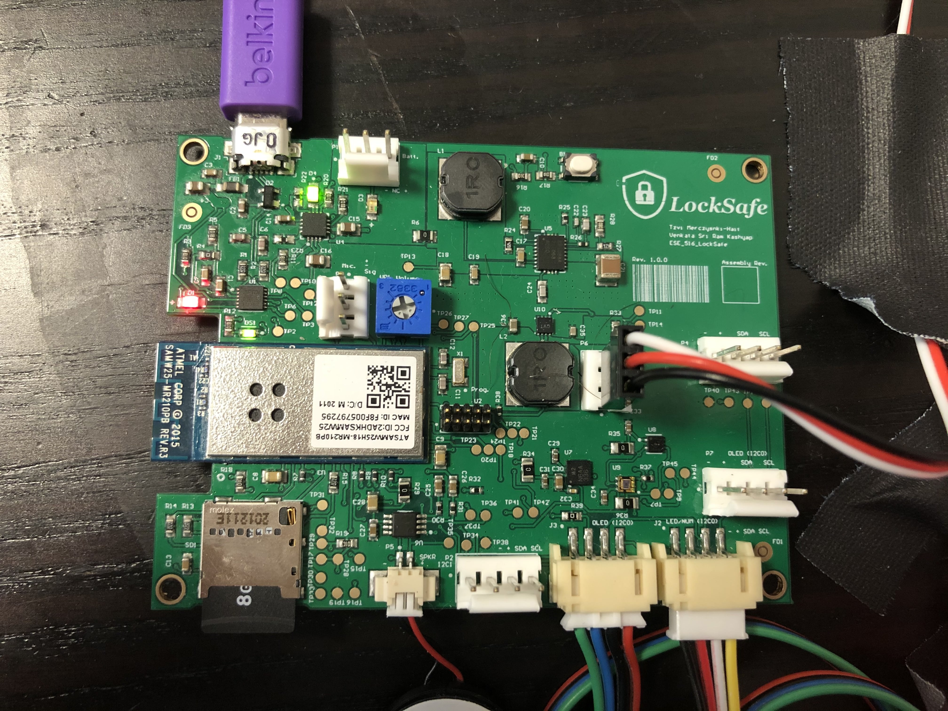
PCB
-

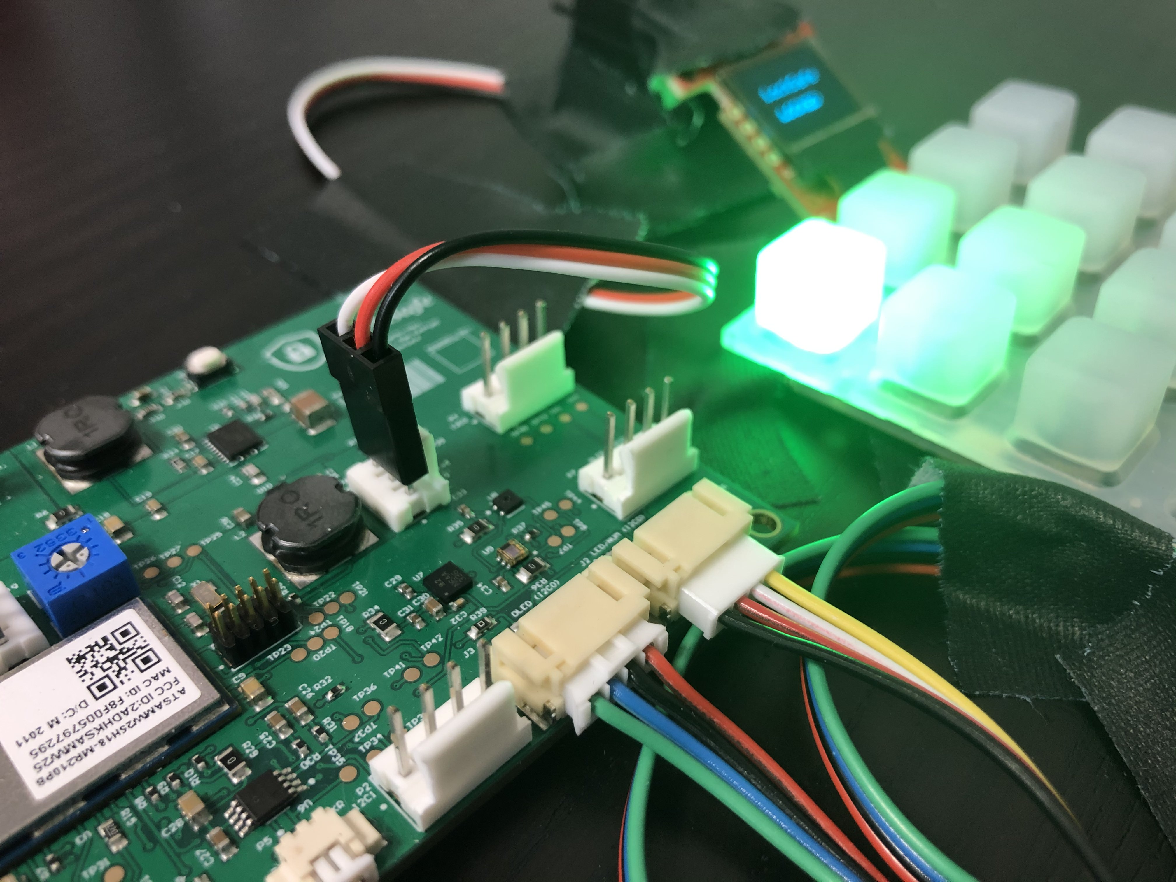
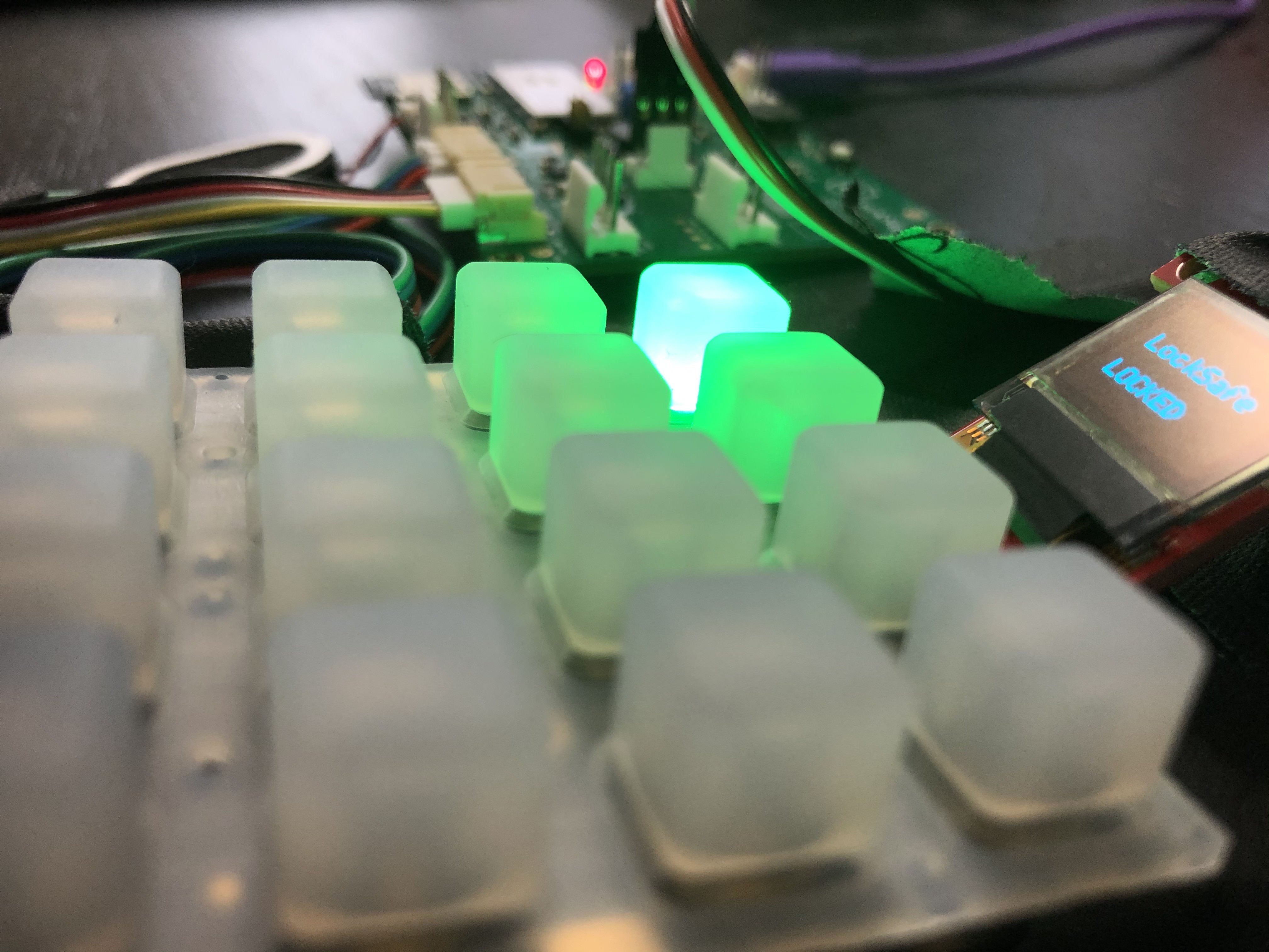
Keypad
-

Screen
-

"All Together"
-

Booting
-

Node Red Dashboard
-

Node Red Backend
-

Altium Schematic
-

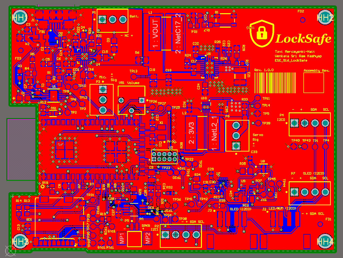
Altium Layout Top
-

Altium 3D View Top
-

Altium Layout Bottom
-

Altium 3D View Bottom
-

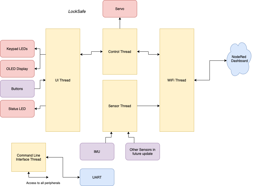
System Diagram
-

Detailed PCB Diagram
-

Firmware Diagram


What it Does
LockSafe is an efficient IoT solution for a smart-lock with single use password generation and telemetry.
The device is a lock for a safe, where you want to not only unlock it without keys, but also have access to data about the movement of the lock (for example to know if someone is stealing it).
LockSafe lets the user view a one time password on the web dashboard and use that to open the lock. It also updates the user, through the web dashboard, about acceleration data of the device. In the future (see below) we can easily add more data for the user such as temperature (is there a fire?).
Inspiration
In this fastly growing digital world, we are seeing that more and more things are getting digitized to make them easy to use. We wanted to make it easy for a user to keep his items secure and also hassle-free at the same time. With LockSafe users not only need not carry keys with them all the time but can also be assured of the safety of the lockbox while away from it.
How it Works
The hardware is centered around a SAMW25 board that has built in WiFi. Below is a block diagram of both the overall system, and a detailed diagram of the components and power architecture.


The firmware system is structured around threads and data travels between them over FreeRTOS queues.
Shown below are the 4 threads:

The UI thread handles updating the keypad and OLED display, as well as passing key inputs to the control thread.
The Control thread handles actuating the lock, and passing data between the WiFi and UI threads. The Sensor thread exclusively queries sensors for data and passes them to the WiFi thread.
A users interaction with the device goes as follows: If the device is unlocked, the user presses a key to lock the device. If the device is locked, the user can press a key to trigger generation of a new passcode viewable on the web dashboard. The user then enters the passcode, which is sent to the web dashboard. There it is compared with the actual passcode, and the dashboard sends back a message to either unlock, or not unlock the device. The password is randomly generated each time, and never transmitted over the air until entered correctly, so it cannot be intercepted while still valuable.
There is also a command line interface (running on its own thread) that one can access over UART for testing, and triggering firmware updates.
Challenges we Ran Into
Component selection for the device was not easy. We needed to constantly check for stock and adjust based on the current market availability.
Developing a small PCB and also being able to integrate all the connections for the sensors was difficult. We had to go through multiple attempts routing the board, and eventually had to make it bigger than originally planned.
While writing the drivers specific to a sensor it is sometimes difficult to find existing drivers that work for our purpose. In those cases we had to go through the data sheet for the device and write the driver ourselves. This could be a difficult and time consuming process.
What we Learned with the Prototype
It was a good idea to include as much hardware as possible on the PCB! During design we made a decision to include many sensors, even if we might not have time to implement drivers and routines for all of them. Looking back at the effort required for hardware development (the effort in layout, the lead times, the part procurement process) this was a good choice. We didn't manage to get all the features we planned into the final product, but we now have an easy path forward to do that with firmware updates.
It’s very easy to make mistakes with the BOM in Altium: we caught errors during multiple passes through it, and learned it’s very important to carefully check that the parts match your schematics.
Similarly, including ports for probes such as the logic analyzer was very useful when debugging firmware.
Checking polarity is important! One of the I2C connectors was reversed, and required us to bend a little plastic to make it work.
What we Learned
We learned more about using Altium software and got hands on experience designing a PCB from scratch
We used features of FreeRTOS and learned principles of thread synchronization and mutual exclusion.
We gained experience developing C in Microchip Studio. Debugging with breakpoints to see stacks and current memory was really helpful.
We learned how to get our data from an embedded system into a useful form for a client: We used MQTT to send data and Node-RED to build a dashboard to handle it.
We implemented Over the Air updates so that in future we can easily improve device functionality.
Sometimes even commercially bought hardware is the issue: We had a NeoTrellis board that wasn’t working, and spent hours debugging it. Simply replacing the board worked perfectly.
We learned how to use TI Webench to design power systems.
Next Steps
Improvements in current iteration
Error Handling
- In particular, handling lost packets during MQTT transmissions and ensuring that the state machines running on our threads recover the proper state correctly
More robust management of system states to ensure unlock commands only work when in valid states
Enclosure for the lock by 3D printing a model that suits our device
Using a high grade servo that cannot be easily rotated as the lock actuator
More useful status updates in client dashboard
Power saving
Get rid of busy waiting in favor of blocking threads
Utilize enable pins that were routed from peripherals to the MCU to only power up the sensors we use and when we use them
New Features
Implement temperature, humidity, ambient light, and sound monitoring
- Allows user to better assess conditions around his locking device to ensure its safety
Implement audio feedback
- (These are all require firmware updates to add drivers and routines for the components already included in the PCB)
Test battery power
Final Thoughts
It’s really exciting to be able to hold a physical product in our hands. We designed it, wrote firmware for it, and it actually works as expected! We learned how to methodically and step by step, go from an idea, through part research, through feasibility studies, through hardware design, through making the hardware work with firmware, and through putting together a presentable product. That’s something we don’t take for granted and something we’re very thankful to ESE516 for helping us accomplish.
Built With
- altium
- c
- microchip-studio
- samd21
- samw25


Log in or sign up for Devpost to join the conversation.