-
-

Line Follower Robot
-

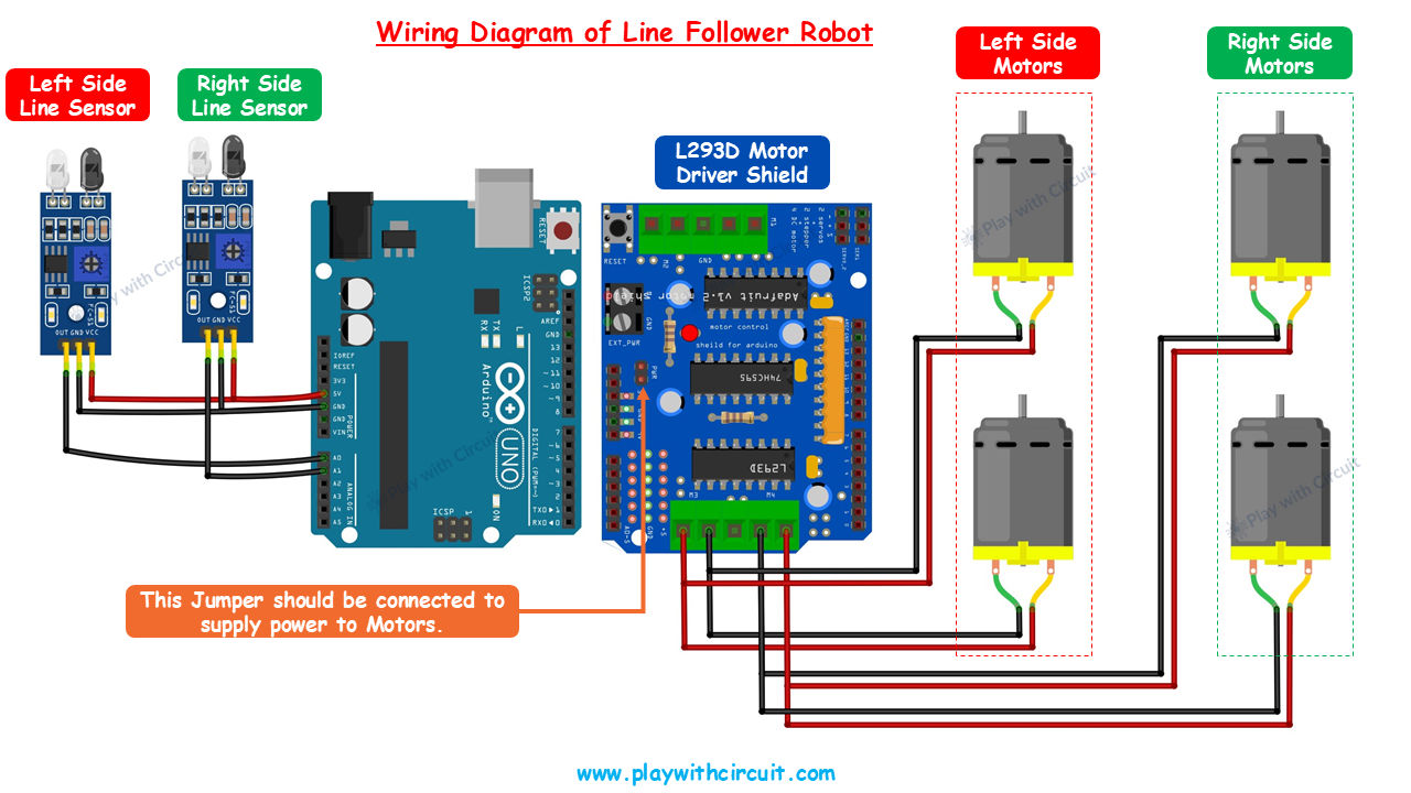
Circuit Diagram
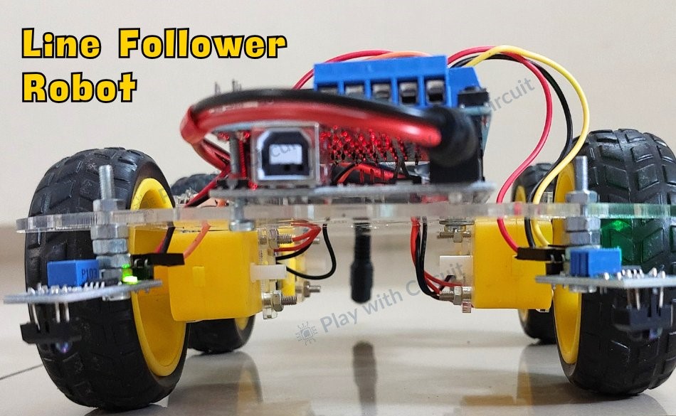
A line follower robot, or LFR, is an autonomous robot that follows a specific path, typically defined by a black line on a white surface or vice versa. These robots are widely used in industrial automation, logistics, and educational projects, showcasing the practical application of robotics and sensors. This guide provides a detailed walkthrough for building an Arduino-based line follower robot.
Line Follower Robot
A line follower robot detects and tracks a line using light properties. Black surfaces absorb most light, while white surfaces reflect it. This difference enables sensors, such as line sensors, to distinguish between the two surfaces. In this tutorial, we’ll use line sensors that combine an infrared (IR) emitter and a receiver. The emitter sends out IR light, and the receiver detects the reflected light. On a white surface: IR light is reflected back to the receiver. On a black line: IR light is absorbed, and little to no light reaches the receiver.
How a Line Follower Robot Navigates
The robot’s movement is controlled by two motors—one on the left and one on the right. Sensors on either side of the robot send signals to the Arduino, which controls the motors accordingly. Here’s how the robot behaves in different scenarios:
- Moving Forward: When both sensors detect a white surface (with the black line between them), the Arduino directs both motors to move forward.
- Turning Left: If the left sensor detects the black line while the right sensor is on the white surface, the left motor slows or reverses, causing the robot to turn left.
- Turning Right: If the right sensor detects the black line while the left sensor is on the white surface, the right motor adjusts, turning the robot to the right.
- Stopping: If both sensors detect the black line simultaneously, the Arduino halts both motors, stopping the robot.
Hardware Requirements
- Arduino UNO R3
- L293D Motor Driver Shield
- 12V Li-ion Batteries
- Jumper Wires
- USB Cable (Type A to B)
- Geared DC Motors
- Wheels
- Robot Chassis
- Line Sensor Modules
- Black Tape (Non-Shiny)
Why Use an L293D Motor Driver Shield?
Motors in a robot require higher voltage and current than the Arduino can provide. The L293D motor driver shield bridges this gap, safely delivering the required power. Additionally, it supports bi-directional control, enabling the motors to rotate in forward or reverse directions. For more details, check out our https://playwithcircuit.com/l293d-motor-driver-shield-arduino-tutorial/.
Step-by-Step Assembly Process
- Preparing the Chassis: Attach all four motors to the chassis and solder wires to their terminals. Attach the wheels to the motors and mount the line sensors at the front. Ensure the sensors are spaced 11–11.5 cm apart and positioned 2 cm above the ground.
- Connecting Components: Attach the motor driver shield to the Arduino and secure it to the chassis. Connect the sensors and motors to the shield as per the circuit diagram.
- Programming the Arduino: Install the required libraries in the Arduino IDE. Upload the provided code to the Arduino.
- Finalizing the Robot: Mount the battery pack at the rear and secure it with tape or ties.
Arduino Line Follower Robot Code
/*
Library used: Adafruit Motor Shield library V1 version: 1.0.1
For this code to run as expected:
1.The centre to centre distance between the Line sensors should be 11 to 11.5 cm
2. The width of black tape should be 4.8 to 5 cm
3. The distance of the sensor LED from the flat ground surface should be 2 cm.
*/
#include <AFMotor.h>
// MACROS for Debug print, while calibrating set its value to 1 else keep it 0
#define DEBUG_PRINT 0
// MACROS for Analog Input
#define LEFT_IR A0
#define RIGHT_IR A1
// MACROS to control the Robot
#define DETECT_LIMIT 300
#define FORWARD_SPEED 60
#define TURN_SHARP_SPEED 150
#define TURN_SLIGHT_SPEED 120
#define DELAY_AFTER_TURN 140
#define BEFORE_TURN_DELAY 10
// BO Motor control related data here
// Here motors are running using M3 and M4 of the shield and Left Motor is connected to M3 and Right Motor is connected to M4 using IC2 of the shield
AF_DCMotor motorL(3);  // Uses PWM0B pin of Arduino Pin 5 for Enable
AF_DCMotor motorR(4);  // Uses PWM0A pin of Arduino Pin 6 for Enable
// variables to store the analog values
int left_value;
int right_value;
// Set the last direction to Stop
char lastDirection = 'S';
void setup() {
#if DEBUG_PRINT
  Serial.begin(9600);
#endif
  // Set the current speed of Left Motor to 0
  motorL.setSpeed(0);
  // turn on motor
  motorL.run(RELEASE);
  // Set the current speed of Right Motor to 0
  motorR.setSpeed(0);
  // turn off motor
  motorR.run(RELEASE);
  // To provide starting push to Robot these values are set
  motorR.run(FORWARD);
  motorL.run(FORWARD);
  motorL.setSpeed(255);
  motorR.setSpeed(255);
  delay(40);  // delay of 40 ms
}
void loop() {
  left_value = analogRead(LEFT_IR);
  right_value = analogRead(RIGHT_IR);
#if DEBUG_PRINT
  // This is for debugging. To check the analog inputs the DETECT_LIMIT MACRO value 300 is set by analysing the debug prints
  Serial.print(left_value);
  Serial.print(",");
  Serial.print(right_value);
  Serial.print(",");
  Serial.print(lastDirection);
  Serial.write(10);
#endif
  // Right Sensor detects black line and left does not detect
  if (right_value >= DETECT_LIMIT && !(left_value >= DETECT_LIMIT)) {
    turnRight();
  }
  // Left Sensor detects black line and right does not detect
  else if ((left_value >= DETECT_LIMIT) && !(right_value >= DETECT_LIMIT)) {
    turnLeft();
  }
  // both sensors doesn't detect black line
  else if (!(left_value >= DETECT_LIMIT) && !(right_value >= DETECT_LIMIT)) {
    moveForward();
  }
  // both sensors detect black line
  else if ((left_value >= DETECT_LIMIT) && (right_value >= DETECT_LIMIT)) {
    stop();
  }
}
void moveForward() {
  if (lastDirection != 'F') {
    // To provide starting push to Robot when last direction was not forward
    motorR.run(FORWARD);
    motorL.run(FORWARD);
    motorL.setSpeed(255);
    motorR.setSpeed(255);
    lastDirection = 'F';
    delay(20);
  } else {
    // If the last direction was forward
    motorR.run(FORWARD);
    motorL.run(FORWARD);
    motorL.setSpeed(FORWARD_SPEED);
    motorR.setSpeed(FORWARD_SPEED);
  }
}
void stop() {
  if (lastDirection != 'S') {
    // When stop is detected move further one time to check if its actual stop or not, needed when the robot turns
    motorR.run(FORWARD);
    motorL.run(FORWARD);
    motorL.setSpeed(255);
    motorR.setSpeed(255);
    lastDirection = 'S';
    delay(40);
  } else {
    // When stop is detected next time then stop the Robot
    motorL.setSpeed(0);
    motorR.setSpeed(0);
    motorL.run(RELEASE);
    motorR.run(RELEASE);
    lastDirection = 'S';
  }
}
void turnRight(void) {
  // If first time Right Turn is taken
  if (lastDirection != 'R') {
    lastDirection = 'R';
    // Stop the motor for some time
    motorL.setSpeed(0);
    motorR.setSpeed(0);
    delay(BEFORE_TURN_DELAY);
    // take Slight Right turn
    motorL.run(FORWARD);
    motorR.run(BACKWARD);
    motorL.setSpeed(TURN_SLIGHT_SPEED);
    motorR.setSpeed(TURN_SLIGHT_SPEED);
  } else {
    // take sharp Right turn
    motorL.run(FORWARD);
    motorR.run(BACKWARD);
    motorL.setSpeed(TURN_SHARP_SPEED);
    motorR.setSpeed(TURN_SHARP_SPEED);
  }
  delay(DELAY_AFTER_TURN);
}
void turnLeft() {
  // If first time Left Turn is taken
  if (lastDirection != 'L') {
    lastDirection = 'L';
    // Stop the motor for some time
    motorL.setSpeed(0);
    motorR.setSpeed(0);
    delay(BEFORE_TURN_DELAY);
    // take slight Left turn
    motorR.run(FORWARD);
    motorL.run(BACKWARD);
    motorL.setSpeed(TURN_SLIGHT_SPEED);
    motorR.setSpeed(TURN_SLIGHT_SPEED);
  } else {
    // take sharp Left turn
    motorR.run(FORWARD);
    motorL.run(BACKWARD);
    motorL.setSpeed(TURN_SHARP_SPEED);
    motorR.setSpeed(TURN_SHARP_SPEED);
  }
  delay(DELAY_AFTER_TURN);
}

Log in or sign up for Devpost to join the conversation.