Inspiration
Many people enjoy playing laser tag, but the opportunities to play are often limited to arcades and special events. Therefore, a self-made laser tag game would solve this problem. Users can play unlimited rounds at no cost as well as customize the game to their liking. As demonstrated by this project, it is possible to build a fully functional laser tag game at low cost.
What it does
Laser tag is a game in which players shoot other players with a directed signal such as IR. The objective of the game is to gather as many kills as possible while minimizing deaths.
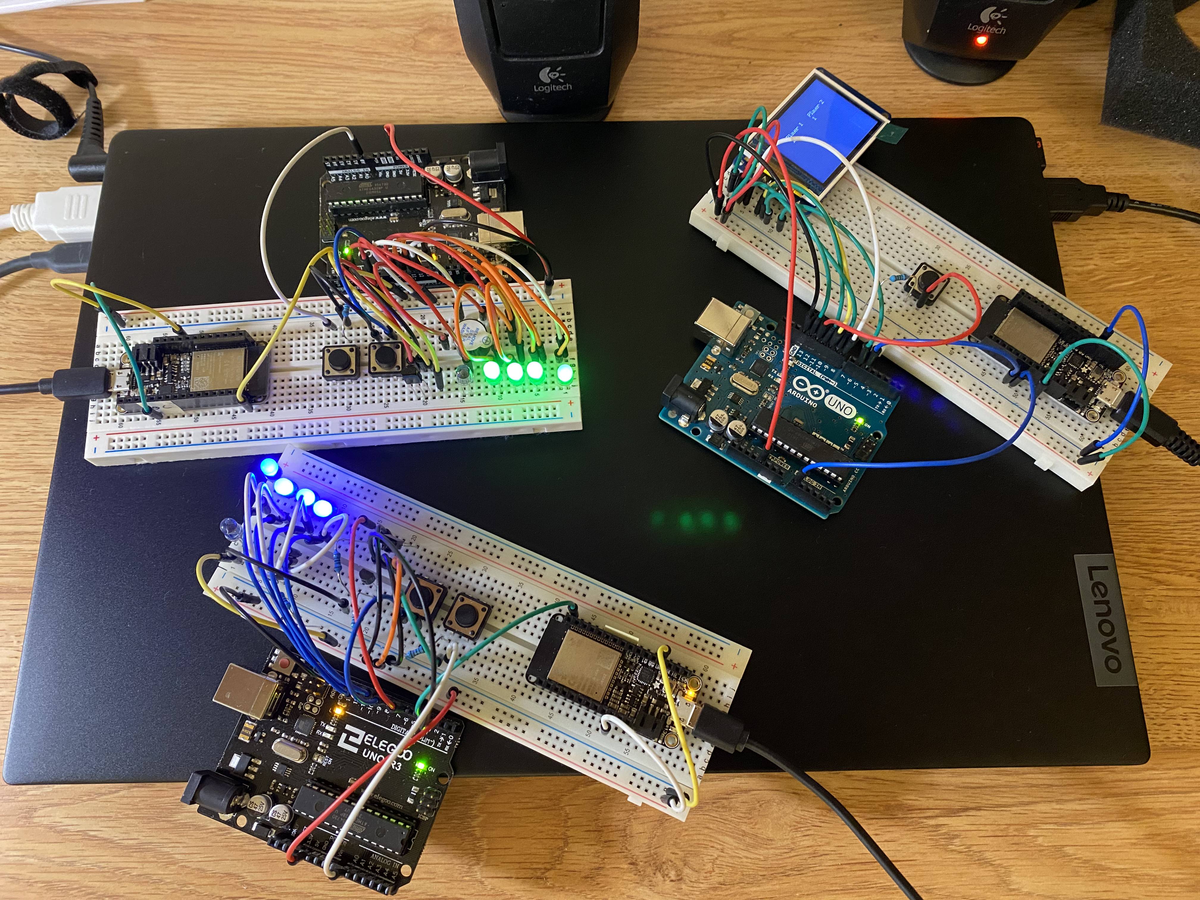
A horizontally scalable, fully functional multiplayer laser tag was designed and constructed. The demo setup consists of two laser tag guns and a controller with a LCD scoreboard. Each laser tag gun has a fire button, a reload button, four LEDs displaying remaining rounds, a speaker, and an ESP32. When a player hits another target, a signal must be sent to the controller to log the event and update the scoreboard. When a player is hit, they are deactivated for several seconds while reviving. They are unable to fire or be hit again during this period. Each player begins with a magazine of four rounds and must reload when the magazine is empty before firing. The ESP32 is used for player-controller communication. The controller has a reset button to begin a new game.
How we built it
The project consists of two components: laser tag guns and central controller displaying the scoreboard.
ATmega328P was chosen as a low-cost, low-power microcontroller for the laser tag guns and central controller.
A modified NEC IR transmission protocol was used: 9ms burst 4.5ms rest identifier bits (8), in which logical 0 is encoded by a 512us burst followed by a 512us rest (1024us total), and logical 1 is encoded by a 512us burst followed by a 1536us rest (2048us total).
The identifier bits are unique to each laser tag gun, which allows a hit target to identify the signal source and relay the event to the controller.
Summary of pins on ATmega328P on Arduino board:
D2 - input from IR sensor
D8 - input from button to fire
A0 - input from button to reload
D3 - output to ESP32 when hit
D4 - output to speaker
D6 - output to IR LED
D9:12 - output to ammo LEDs
TSOP38238 IR sensor detects 38kHz signals from IR led on each gun and outputs a demodulated signal to pin D2.
IR333-A IR LED is paired with a 100 Ohm resistor in series with an NPN transistor fed by a 5V line and modulated by pin D6 at 38kHz.
Timer0 is set to CTC mode and hardware toggles OC0A pin (PD6). Timer2 is set to normal mode with output compare interrupt A, in which OCR2A is changed to adjust the length of IR pulses by toggling COM0A0. Timer1 is set to normal mode with overflow interrupt and output compare interrupt A and B.
Overflow interrupt is used to revive the player after being hit as well as reload by counting the number of overflows since the initial event. Interrupt A is used to toggle the speaker and LEDs when hit. Interrupt B is used to turn off the speaker and fire LED after firing.
Three pin change interrupts are used:
PCINT0 - B0 (internal pull up resistor enabled) Pressing the fire button, which is connected to ground, triggers a falling edge change. The button is implicitly debounced in software through the cooldown logic, in which one full cycle of Timer1 must elapse before the player can fire again.
PCINT1 - C0 (internal pull up resistor enabled) Pressing the reload button, which is connected ground, triggers a falling edge change. The button is implicitly debounced in software through the reload logic, in which three full cycles of Timer1 in addition to one overflow after the first press must elapse before the player can trigger any new actions. Using the overflow naturally introduces randomness in reload time needed for the first shot.
PCINT2 - D5 (internal pull up resistor enabled) When a target is hit, it sends a signal to the controller, which relays a signal to the source, and the ESP32 toggles the input to D5. The player receives the signal and triggers a LED and buzzer.
Polling was used to read IR signal because the signal is inherently sequential, and using the main loop enables fine control over reading the signal. Polling also avoids reading in noise such as a short signal change. A loop waits for the first high signal, then starts recording the length of each pulse and rest in an array. When any signal has not changed for 10ms, it is regarded as a timeout. The recorded signal is then processed. The first pulse and rest are checked for the 9ms and 4.5ms standard. Then, the identifier bits are compared to self. If different, then the ESP32 relays the signal to the controller.
Challenges we ran into and what we learned
This project demonstrated the importance of reading the datasheet, which stated that the sensor was tuned to 38kHz and would filter out background noise. In the beginning, I did not use a 38kHz pulse and instead toggled the IR led on. The sensor would not record any signal as a result. Then, when I used a 38kHz signal, the initial pulse was recorded but the sensor filtered out all further pulses, so I was not able to get any more signal. This is because the sensor tunes out the signal after a period of time since the sensor is designed to receive short pulses from a remote control or similar application.
This project also exposes the pitfalls of using UART print statements to debug, particularly in time critical applications such as wireless communication, where events are on the microsecond scale. More generally, in best practice, interrupts should be extremely short and only set a flag for the main loop to process. Even by moving UART calls out of interrupts and using a flag to run the UART in the main loop, the time consuming calls interfere with the main process. At one point, I faced a situation in which a remote control could correctly trigger both targets, but each target could only correctly read the signal generated by itself. This was extremely confusing because clearly each target is capable of reading an IR signal. Additionally, each target was able to read the IR signal generated by itself. However, the other target read an unusual IR signal. The issue was that UART debug statements delayed everything in the target by the same duration so that the signal recorded in software was correct, but the signal actually generated was incorrect from delays caused by UART.
Accomplishments that we're proud of
The laser tag system design allows horizontal scalability by assigning a unique 8-bit identifier to each laser tag gun. This allows for 256 players. If needed, a 16-bit identifier can easily be used, which allows for 65536 players, more than will be needed.
What's next for Laser Tag
Range and angle resolution is an issue with the current laser tag guns. Therefore, a tube and a convex lens can be used to produce a more intense, directed beam of IR. Multiple IR LEDs can also be used in parallel to increase intensity.
Scoreboard and gameplay customization can be added. Custom names, point thresholds, rounds per reload, and damage can be added to increase game complexity.
The laser tag guns use the ESP32's WiFi capabilities to communicate, but WiFi has limited range and is affected by physical obstacles such as walls. A radio transmitter and receiver is cheaper, has much greater range, and is less affected by physical objects.
Built With
- atmega328p
- c
- esp32
- infrared
Log in or sign up for Devpost to join the conversation.