-
-

Altium Rendered version
-

-

-

-
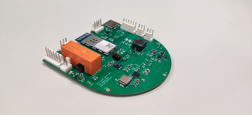
Final PCB
-

-

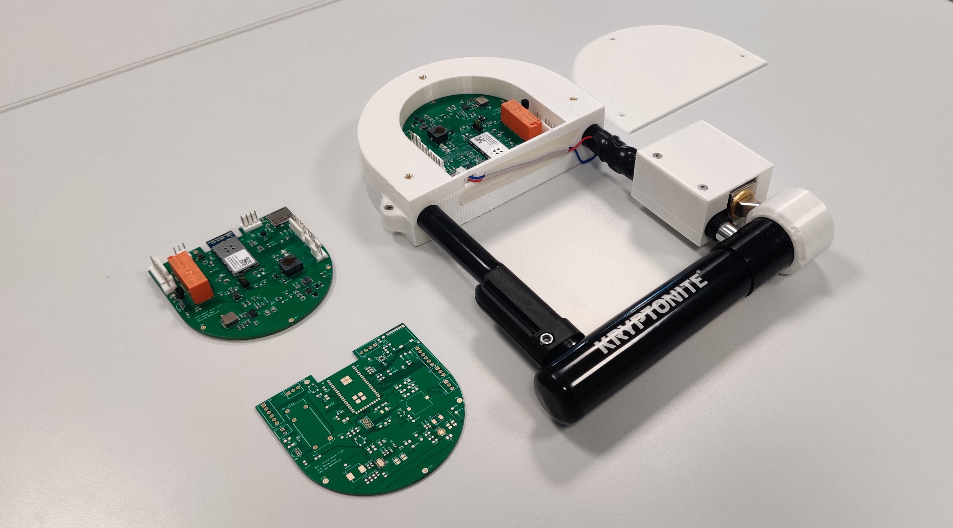
Final Prototype
-

-

Assembled and unassembled PCB's
-

-

-

KOIN Bike lock deployed
-

Node-Red dashboard
-

Node-Red backend
-

block diagram


Inspiration
Bike thefts are very common in the university area and most of them occur during the day. I stopped a bike theft just by calling out someone who was trying to steal my friend’s bike. I realized that all that is required to stop a theft is to gather the attention of the people around. The KOIN lock provides a solution to this pain point by setting a siren when the bike lock experiences strong jitters, or when motion is detected while the lock status is still locked. With our KOIN lock, we wish more university students will feel safer and comfortable commuting and traveling by bike.
Secondly, sometimes the bike owner is close enough and needs to leave the bike in an unsafe area for a small duration. The risk in this situation is eliminated by the KOIN lock as it quickly sends an alert to the owner when some suspicious activity is detected.
What it does
The KOIN lock is a ‘bike’ lock that prevents bike theft by warding off thieves. When the inertial measurement unit (IMU) inside the device detects an unusual motion of a lock that indicates a potential theft activity, the KOIN lock triggers the following activities.
- Sets an alarm to draw the attention of bystanders
- Sends an alert to the registered users of the KOIN lock.
Additionally, the users can lock and unlock the KOIN lock remotely and use the buzzer trigger feature to find their bike when parked in a big lot.
How we built it
The PCB is designed in Altium and was fabricated and assembled by PCBway. We used tools like a labrador oscilloscope, logic analyzer, the Jlink mini edu to bring up the PCB. The mechanical assembly is based on a regular bikelock and has 3D printed parts that were designed and printed in-house to complete an elegant prototype.
Challenges we ran into
There were endless challenges. Here are a few examples. Component Selection: There are so many different brands and types that ultimately do the same function (i.e. buzzer). Having too many choices actually can be time-consuming. Also, due to COVID, some components were going out of stock.
Driver Development: drivers provided by the manufacturers were usually for Arduino, python or c++. Developing a camera driver was especially difficult. In order to understand the communications between MCU and the camera module, a logic analyzer was used. When the logic analyzer was directly connected to MCU it could read signals but when the logic analyzer, MCU and camera module were all connected together on the breadboard, the logic analyzer could not pick up any signals.
Hardware Debugging: Unlike pure software program debugging, hardware debugging was difficult because there were so many potential causes of problems that are hard to navigate and troubleshoot. There are many layers of abstraction in sensors, actuators and other components in a device, it is difficult to find where specifically and how it is failing.
Accomplishments that we're proud of
We're proud of the fact that we started from scratch without any practical knowledge of PCB design and ended up designing a complete prototype that is also a great portfolio piece. The class became more challenging for our team when we moved to RTOS but we're proud of how we learnt and navigated through the coding challenges. (Thanks to the teaching staff who was always available to help)
What we learned
Looking back, we learned so much during this course. Here are some of the highlights. PCB Design and Manufacturing: We designed a 4 layered PCB and learned good practices for PCB design, the logic behind design rules, how PCB design differs for a high-frequency system, things to consider while designing a battery management system etc.
Tools and Softwares: Altium Studio, Microchip Studio, TI webench, Atmel Start, logic analyzer, Percepio, Github, yEd, MQTT related software
Coding for embedded systems: we learned the basics of freeRTOS, Atmel Hardware abstraction layer called the ASF and even writing drivers for different drivers. The class also gave intro bootloaders and OTAFU. We learned good practices like organizing code in .c and .h files and not dumping everything in the main code.
PCB basic skills: good practice of soldering, and bringing a PCB to life.
What's next for KOIN Smart Bike lock
The next steps for us to take the project from a proof of concept stage to the final product are:
- Reducing the overall size of PCB
- Developing a phone app
- Refining the mechanical assembly
- Resolving minor details like adding mounting holes to PCB, relocating headers etc.
- Field testing of the device
- Exploring a rechargeable battery prototype
Node-red dashboard link: link
Click an arrow next to the demo video to check out other cool photos of our PCB and KOIN lock!
Built With
- altium
- atmelstudio
- c++
- freertos
- nodered


Log in or sign up for Devpost to join the conversation.