-
-
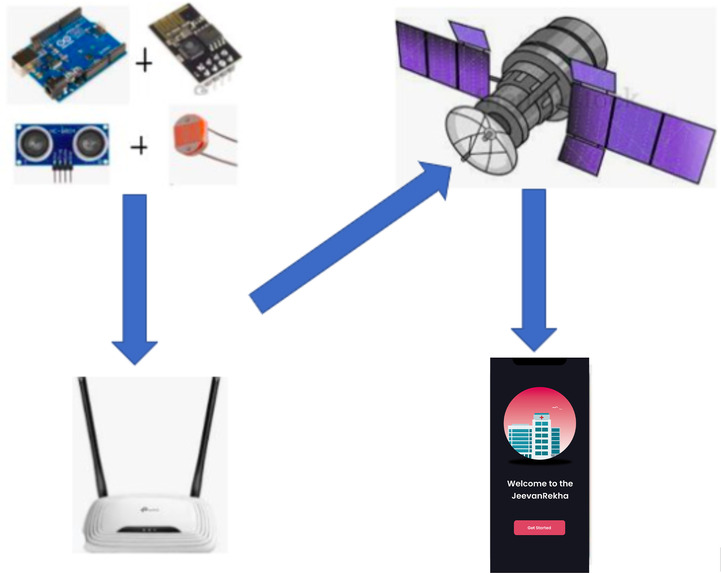
Block diagram
-
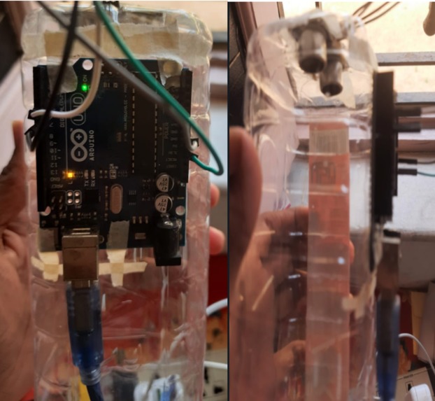
Arduino connected with drip monitor
-
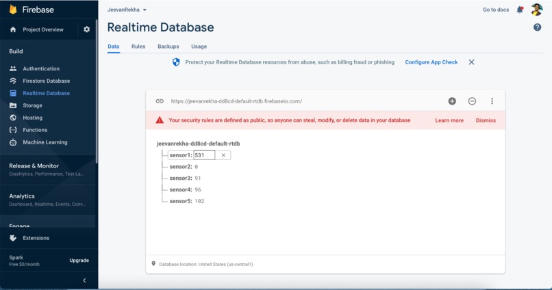
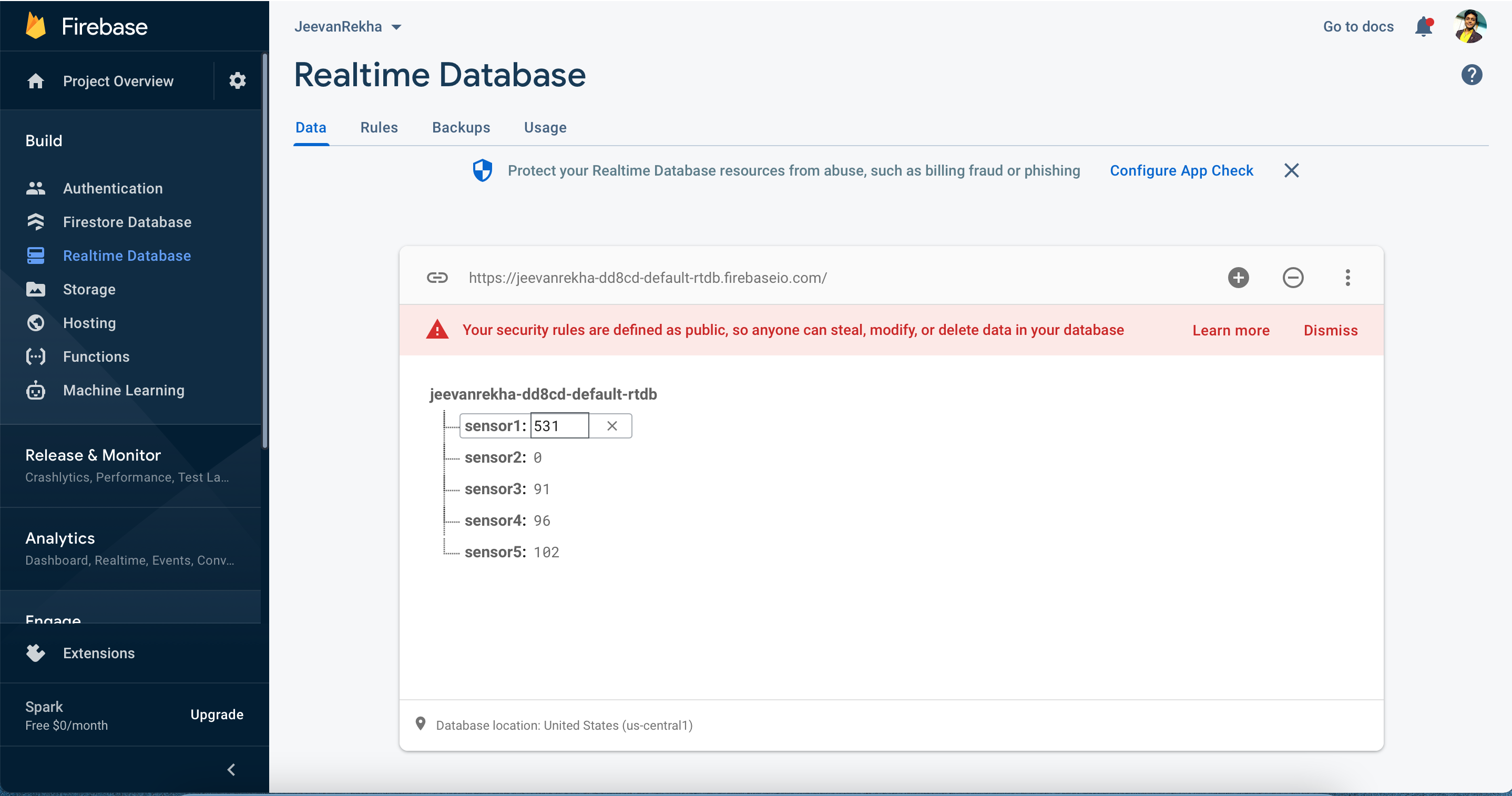
Firebase
-

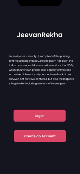
APP VIEW
-
APP VIEW
-
APP VIEW
-

APP VIEW


IOT tool to monitor patients health remotely
ABSTRACT
Today's era of the healthcare system has a very big ILL impact due to poor health monitoring of patients due to various circumstances.Regular health checks can identify any early signs of health issues and prompt us to maintain a healthy lifestyle. Our goal is to provide the users with an improved form of healthcare facilities at a reasonable cost that has faster disease diagnosis, proactive treatment and error reduction. Keeping all that in mind we introduce you to the iOS-based app, Jeevan-Rekha. Jeevan Rekha will allow any medical staff, doctor to view their patient’s information and current health status and reports. Family members of the patient also can view various useful data. Doctors and staff will get a notification when the reports will show any critical situation which will help to save the lives of different patients in an emergency situation. It also helps in the collection of data on a patients’ drip level, oxygen saturation level, pulse rate, etc. The idea is implemented by sending sensor's and device data to clouds and fetching those data to our application and using those data to show and record it for future purposes.
This project is designed to greatly increase the efficiency of the hospital staff as a whole. By not having to conduct manual routine checks on the drip levels, drip conditions, Temperature, heartbeat, oxygen rate and Blood pressure of every patient, the workload of the hospital staff is exceedingly diminished. Thus, automation is an essential step towards providing more efficient, effective and convenient healthcare facilities to all.
PROBLEM STATEMENT
Today's era of healthcare system has a very big ILL impact due to poor health monitoring of patients due to various circumstances.
📍 Diseases that can be noticed easily , pass unnoticed, which in turn contribute to a bigger health hazard.
📍 In various conditions it is impossible to have manual check in regular time interval if the patient’s condition is becoming worse in between then it creates a emergency situation.
📍 Risk assessment for any disease/ medical condition can be estimated and changes in regular lifestyle can be made accordingly.
📍 Poor health monitoring can cause a case of denial for the disease in case of “sudden” appearance of the disease.
📍 It can also psychologically effect patient as he might be scared that a disease would pop up if he goes for a checkup.
📍 Regular health checks can identify any early signs of health issues.
📍 Prompt you to maintain a healthy lifestyle.
📍 When you have a check, your doctor will talk to you about your medical history, your family’s history of disease and your lifestyle. Your diet, weight, how much you exercise, and whether or not you smoke and drink alcohol or take illegal drugs will also be discussed.
📍 If you have high-risk factors, such as a family history of a condition, it may be more likely that you will develop a particular disease. Regular checks may help your doctor pick up early warning signs.
OUR GOAL
✨ Cost Reduction: IoT enables patient monitoring in real time, thus significantly cutting down unnecessary visits to doctors, hospital stays and re-admissions.
✨ Improved Treatment: It enables physicians to make evidencebased informed decisions and brings absolute transparency.
✨ Faster Disease Diagnosis: Continuous patient monitoring and real time data helps in diagnosing diseases at an early stage or even before the disease develops based on symptoms.
✨ Proactive Treatment: Continuous health monitoring opens the doors for providing proactive medical treatment.
✨ Drugs and Equipment Management: Management of drugs and medical equipment is a major challenge in a healthcare industry. Through connected devices, these are managed and utilized efficiently with reduced costs.
✨ Error Reduction: Data generated through IoT devices not only help in effective decision making but also ensure smooth healthcare operations with reduced errors, waste and system costs.
OUR SOLUTION
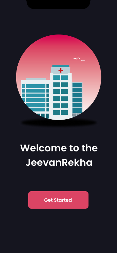
We are introducing an IOS based application which is JeevanRekha.
❄️ JevanRekha will allow any medical staff, doctor to view their patient’s information and current health status and reports.
❄️ Family members of the patient also can view various useful data.
❄️ Doctors and staffs will get a notification when the reports will show any critical situation which will helps to save the lives of different patient in emergency situation.
• We are collecting data of
• Drip level
• Oxygen saturation level
• Pulse rate
• Electrocardiogram data (optional)
We will implement our idea by sending sensor's and device data to clouds and fetch those data to our application and use those data to show and record it for future purpose.
PROJECT DESCRIPTION
This project greatly increases the efficiency of the hospital staff as a whole. The pandemic has led to a lot of hospitals being completely occupied, and the hospital staff overwhelmed. By not having to conduct manual routine checks on the drip levels, drip conditions, Temperature, heartbeat, oxygen rate and Blood pressure of every patient, the workload of the hospital staff is exceedingly diminished. Automation in such essential tasks is the next step towards providing more efficient and convenient healthcare.
Block diagram:
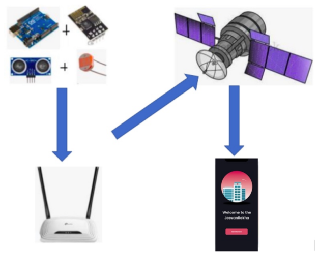
The device and sensor’s data will be transferred to arduino and arduino in turn sends that data to cloud and from the database the data will be fetched and to the application and will be used and stored to generate reports.
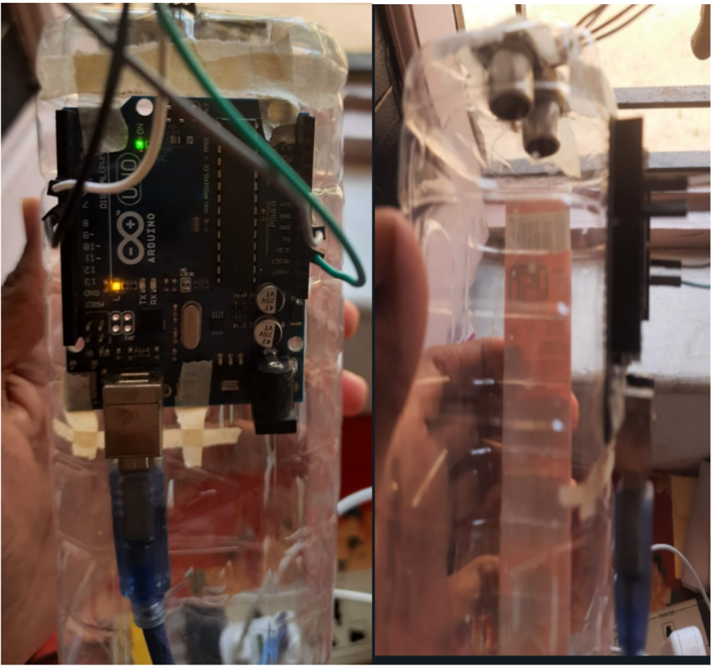
THE DRIP MONITORING SYSTEM
This system elaborates a way to efficiently monitor the drip level at hospitals, while also detecting any bubble formation in the liquid used; a process that is currently done manually by nurses when they periodically check the drip.
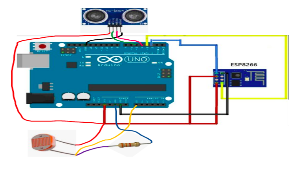
Hardware Requirements and Arrangement:
- Arduino Uno
- HCSR-04 Ultrasonic sensor
- Photo-resistor/light sensor
- Light source
- Esp8266-01 Wifi module
The Arduino Uno is connected to the ESP8266 module, and two sensors(HCSR04 and the LDR). The Ultrasonic sensor has been attached to the bottom of an inverted plastic bottle, which is acting as a drip for demonstration purposes. The LDR has been tucked away inside the bottlecap. The sensor data is fetched and calculated using the Arduino Uno. The calculated sensor values are conveyed to the Thingspeak website via the ESP8266 module.
Working :
The block diagram above represents the correct working of the model in that first it will measure the level of solution left in the bottle through the ultrasonic sensor and if there are any bubbles formed in that solution and due to which there is an obstacle in the path of flowing the solution through a drip that will be detected by the LDR(light dependent resistor). The data produced by the ultrasonic and LDR will be sent to the firebase through that again it will be sent to the Mobile APP and according to the data received by app, there will certain warnings that whether the solution is about to finish or if there are any bubbles formed in that solution or not.
Implementation :
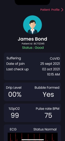
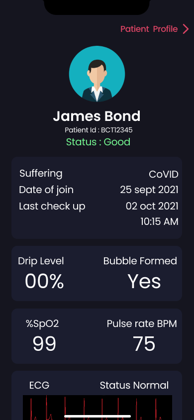
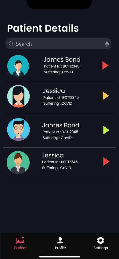
JEEVANREKHA APPLICATION:
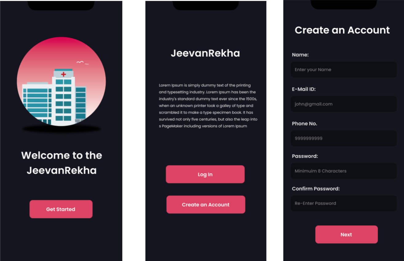
JeevanRekha application will be an IOS application having all the features as described and in future this application will be also available in other operating systems. It will allows to create account and do log in for different type of users.
While creating an account it will ask for the profile type of the user , if the user is a doctor and a staff he or she will be verified and validated then the person will be a registered user and can log in and run the application.
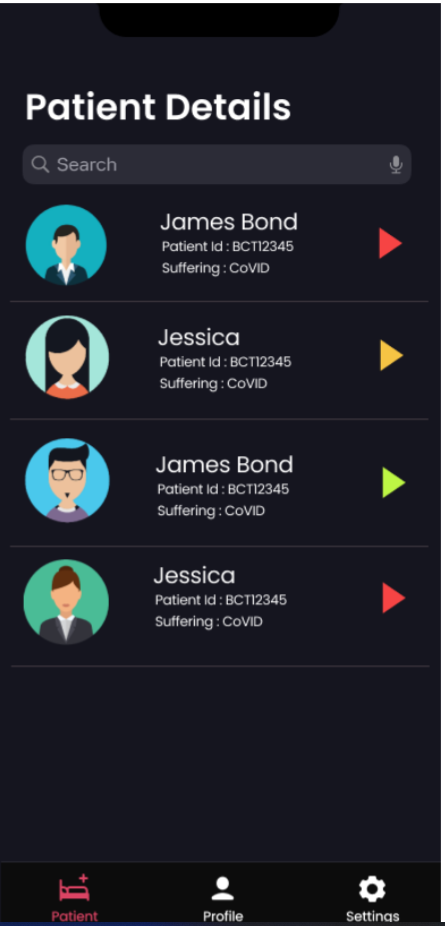
Under the Patient details where we can find search bar where we can search by patient name and patient id The indicator shows the status of the patient.
💥Red indicates patient's report shows its emergency and need doctor immediately.
💥Orange indicates intermediate stage needs staff monitoring.
💥Green indicates Patient's reports are safe.
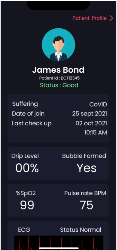
By clicking any profile in the patient detail page user will be directed to this patient information page. After opening brief details of each patient user can view various health status of the patient and also by clicking on patient profile you check the patient profile which will contain previous records.
The proposed solution is going to help the hospital staff in a very fruitful manner through which they need not visit the patient's room repeatedly just for checking the usefull infromation and also notify to doctors and staffs in emergency situation directly. We have successfully solved this problem in a virtual format using IoT
OXYGEN LEVEL MONITORING SYSTEM
Why do we need to check a patient's oxygen level?
Pulse oximetry is a test used to measure the oxygen level (oxygen saturation) of the blood. It is an easy, painless measure of how well oxygen is being sent to parts of your body furthest from your heart, such as the arms and legs.
During or after surgery or procedures that use sedation
🧊 To see how well lung medicines are working
🧊 To check a person’s ability to handle increased activity levels
🧊 To see if a ventilator is needed to help with breathing, or to see how well it’s working
🧊 To check a person has moments when breathing stops during sleep (sleep apnea)
How do we check manually?
A clip-like device called a probe is placed on a body part, such as a finger or ear lobe. The probe uses light to measure how much oxygen is in the blood. The probe may be left on for ongoing monitoring. Or it may be used to take a single reading. The probe will be removed after the test.
Advantages:-
🪁 Monitoring oxygen saturation over time.
🪁 Alerting to dangerously low oxygen levels, particularly in new-borns.
🪁 Offering peace of mind to people with chronic respiratory or cardiovascular conditions.
🪁 Assessing the need for supplemental oxygen.
🪁 Monitoring oxygen saturation levels in people under anaesthesia.
🪁 Indicating dangerous side effects in people taking drugs that affect breathing or oxygen saturation.
Implementation:
MAX30100 is an integrated pulse oximeter and heart-rate monitor sensor solution. It’s an optical sensor that derives its readings from emitting two wavelengths of light from two
LEDs – a red and an infrared one
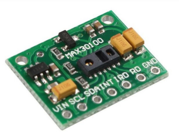
– then measuring the absorbance of pulsing blood through a photodetector. This particular LED colour combination is optimized for reading the data through the tip of one’s finger. It is fully configurable through software registers and the digital output data is stored in a 16-deep FIFO within the device. It has an I2C digital interface to communicate with a host microcontroller. This sensor will be connected to Arduino and the data received from the sensor will be received in the Arduino.
BLOOD PRESSURE AND PULSE RATE MONITORING SYSTEM
Why should we need to check a patient's blood pressure?
Measuring our blood pressure regularly will help our health care team to diagnose any health problems in the early stage. Then we can take steps to control your blood pressure if it is too high or too low. Measuring our blood pressure is the only way to know whether we have high blood
pressure or low blood pressure.
If we are diagnosed with high blood pressure, we can comply with medications to treat it. Untreated high blood pressure leads to stroke, heart attack, kidney failure and heart failure. We should get our blood pressure checked regularly because high blood pressure is a silent killer. There are often no symptoms of this potentially deadly condition.
Advantage:-
Blood pressure monitoring is an important way of diagnosing hypertension and your cardiovascular health. Doing it allows doctors to carry out additional checks that are useful in evaluating the progress of the blood pressure, using diagnostic plans laid down by the European Society of Hypertension.
Implementation:-
Pulse Sensor is a low cost, very small size a plug-and-play heart rate sensor for Arduino and Arduino compatible boards. It is an optical heart rate sensor measures pulse waves, which are changes in the volume of a blood vessel that occur when the heart pumps blood. Pulse waves are detected by measuring the change in volume using an optical sensor and green LED.
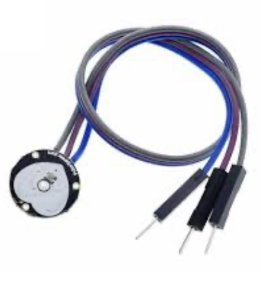
Pulse sensors using the photoelectric pulse wave method are classified into 2 types depending on the measurement method: transmission and reflection. Transmission types measure pulse waves by emitting red or infrared light from the body surface and detecting the change in blood flow during heart beats as a change in the amount of light transmitted through the body. This method is limited to areas where light can easily penetrate, such as the fingertip or earlobe.
Reflection-type pulse sensors (Optical Sensors for Heart Rate Monitor) emit infrared, red, or green light (~550nm) towards the body and measure the amount of light reflected using a photodiode or phototransistor.
Oxygenated haemoglobin present in the blood of the arteries has the characteristic of absorbing incident light, so by sensing the blood flow rate (change in blood vessel volume) that changes following heart contractions over time we are able to measure the pulse wave signal.
CARDIAC MONITORING SYSTEM:
Why should we need to check a patient's Cardiogram data?
An electrocardiogram(ECG) is a simple test that can be used to check the heart’s rhythm and electrical activity. It can be used to investigate symptoms of a possible heart problem such as chest pain, palpitations, dizziness, and shortness of breath.
An ECG can help you detect:
💡 Arrhythmias- where the heart beats too slowly, too quickly, or too irregularly.
💡 Coronary heart disease- where the heart’s blood supply is blocked or interrupted by a build-up of fatty substances.
💡 Heart attacks-where the supply of the blood to the heart is suddenly blocked.
💡 Cardiomyopathy-where the heart wall become thickened or enlarged.
All of the diseases are either fatal on their own or can lead some chronic problem.
Implementation:-
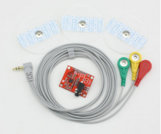
An ECG can be implemented through AD8232 ECG Monitor Sensor Module(shown in the picture above). This is a cost-effective ECG sensor used to measure the electrical activity of the heart. This electrical activity can be charted as an ECG or electrocardiogram and output as an analog reading. The AD8232 module breaks out nine connections from the IC that you can solder pins, wires, or other connectors to. SDN, LO+, LO-, OUTPUT, 3.3V, GND provide essential pins for operating this monitor with an Arduino or other development board. Also provided on this board are RA (Right Arm), LA (Left Arm), and RL (Right Leg) pins to attach and use your own custom sensors. Additionally, there is an LED indicator light that will pulsate to the rhythm of a heartbeat. This sensor will be connected to the Arduino and all the data will be fetched into it and all the data sent to cloud and it is converted to proper graphical format.
TEMPRATURE MONITORING SYSTEM
A temperature monitoring system has become an essential part of healthcare, hospitals, clinics, food business, and other industries in recent years. Measuring body temperature is very important in medicine. A number of diseases are characterised by a change in body temperature. With other illnesses, the course of the disease can be followed by measuring body temperature. This allows the doctor to analyse the effectiveness of treatments based on body temperatures. A fever is the reaction to a disease-specific stimuli. The body changes its normal temperature to support the body’s own defence mechanisms. Fever is the most common form of disease-related (pathological) increase in body temperature. By understanding your own individual body temperature, noticing changes that might indicate an infection, and taking immediate measures to prevent spreading it to others, you can help family, friends, and co-workers stay safe, healthy, and productive.
Implementation:
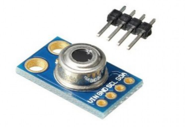
The MLX90614 ESF is an Infra-Red thermometer for non-contact temperature measurements. Both the IR sensitive thermopile detector chip and the signal conditioning ASIC are integrated into the same TO39 can. The Integrated MLX90614 GY-906 is a low noise amplifier, 17- bit ADC, and powerful DSP unit thus achieving high accuracy and resolution of the thermometer.
The user can configure the digital output to be PWM. As a standard, the 10-bit PWM is configured to continuously transmit the measured temperature in the range of -20 to 120 C, with an output resolution of 0.14 C.
This sensor will be connected to the Arduino and all the data will be fetched into it and all the data sent to cloud
ARDUINO UNO
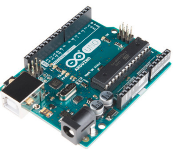
Arduino Uno is a microcontroller board based on the ATmega328P (datasheet). It has 14 digital input/output pins (of which 6 can be used as PWM outputs), 6 analog inputs, a 16 MHz ceramic resonator (CSTCE16M0V53-R0), a USB connection, a power jack, an ICSP header, and a reset button. It contains everything needed to support the microcontroller; simply connect it to a computer with a USB cable or power it with an AC-to-DC adapter or battery to get started. You can tinker with your Uno without worrying too much about doing something wrong, in the worst-case scenario you can replace the chip for a few dollars and start over again.
Esp8266 NodeMcu
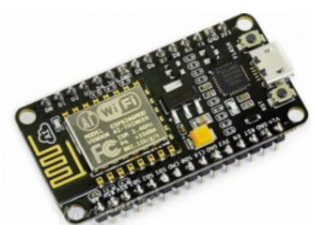
The ESP8266 WIFI Module is a self-contained SOC with an integrated TCP/IP protocol stack that can give any microcontroller access to your WIFI network. The ESP8266 is capable of either hosting an application or offloading all WIFI networking functions from another application processor. Each ESP8266 module comes pre-programmed with an AT command set firmware, meaning, you can simply hook this up to your Arduino device and get about as much WIFI-ability as a WIFI Shield offers (and that's just out of the box)! The ESP8266 module is an extremely cost-effective board with a huge, and ever-growing, community.This module has a powerful enough onboard processing and storage capability that allows it to be integrated with the sensors and other application-specific devices through its GPIOs with minimal development up-front and minimal loading during runtime. Its high degree of on-chip integration allows for minimal external circuitry, including the front-end module, which is designed to occupy a minimal PCB area. The ESP8266 supports APSD for VoIP applications and Bluetooth co-existence interfaces, it contains a self-calibrated RF allowing it to work under all operating conditions and requires no external RF parts.
Figma Link:
https://www.figma.com/file/MLy0TuVyxvDLx6SglWytlL/Untitled?node-id=0%3A1


Log in or sign up for Devpost to join the conversation.