-
-
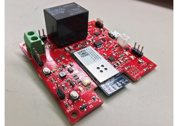
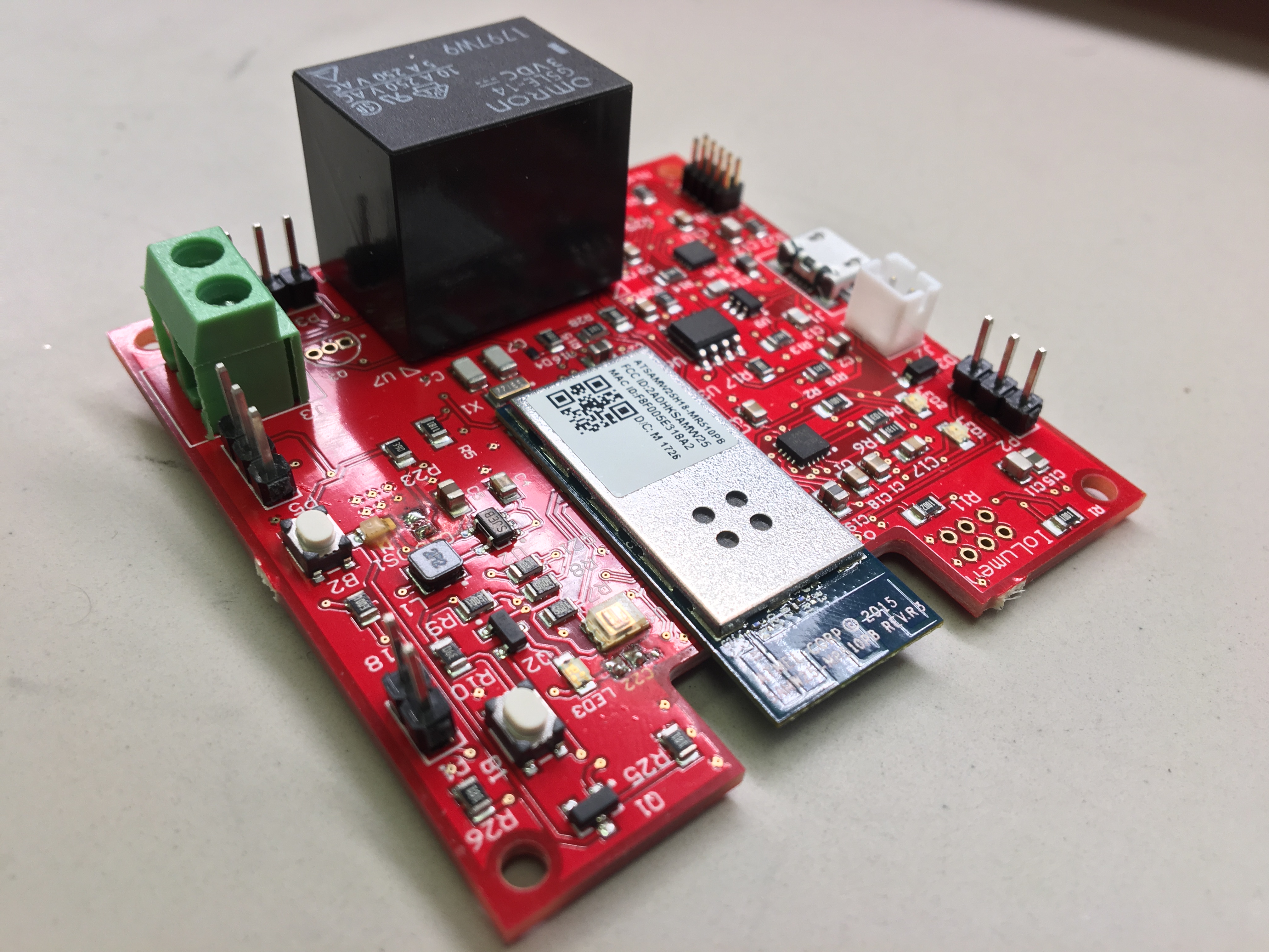
IoLumen
-
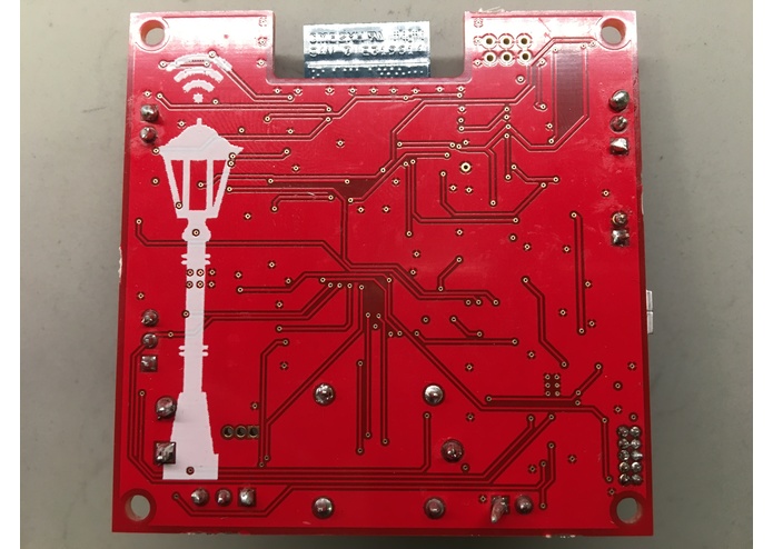
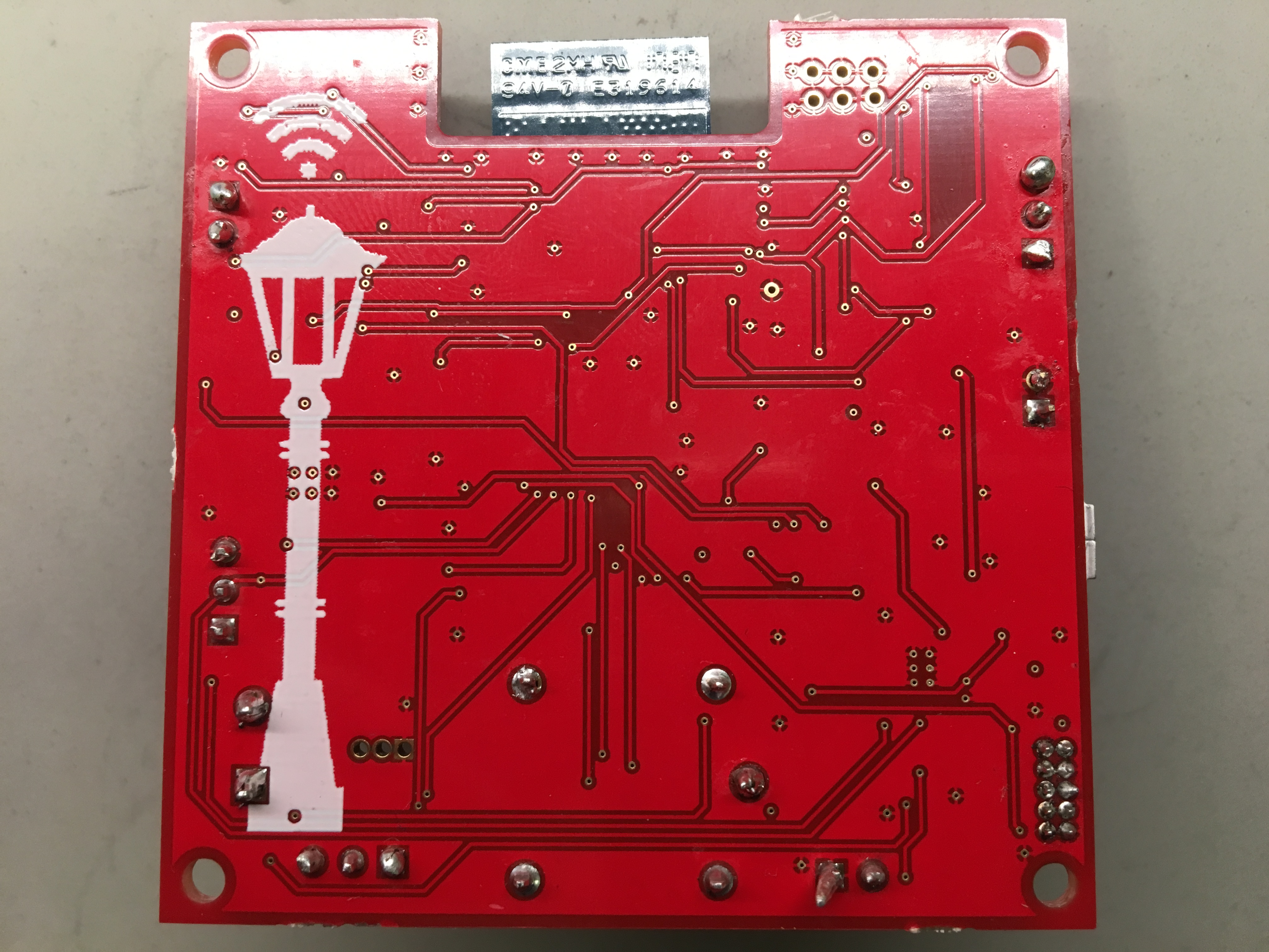
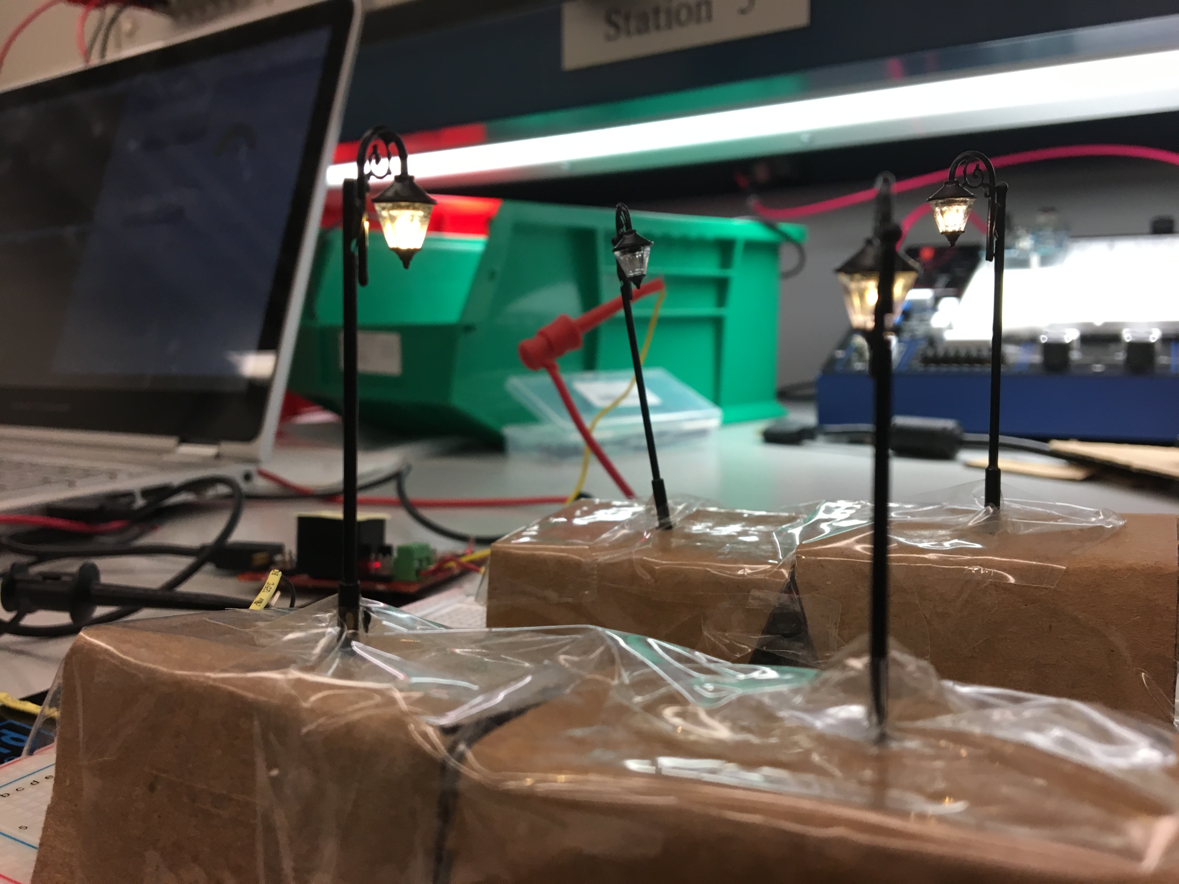
Bottom Layer
-
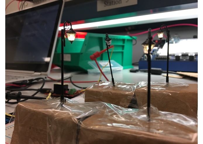
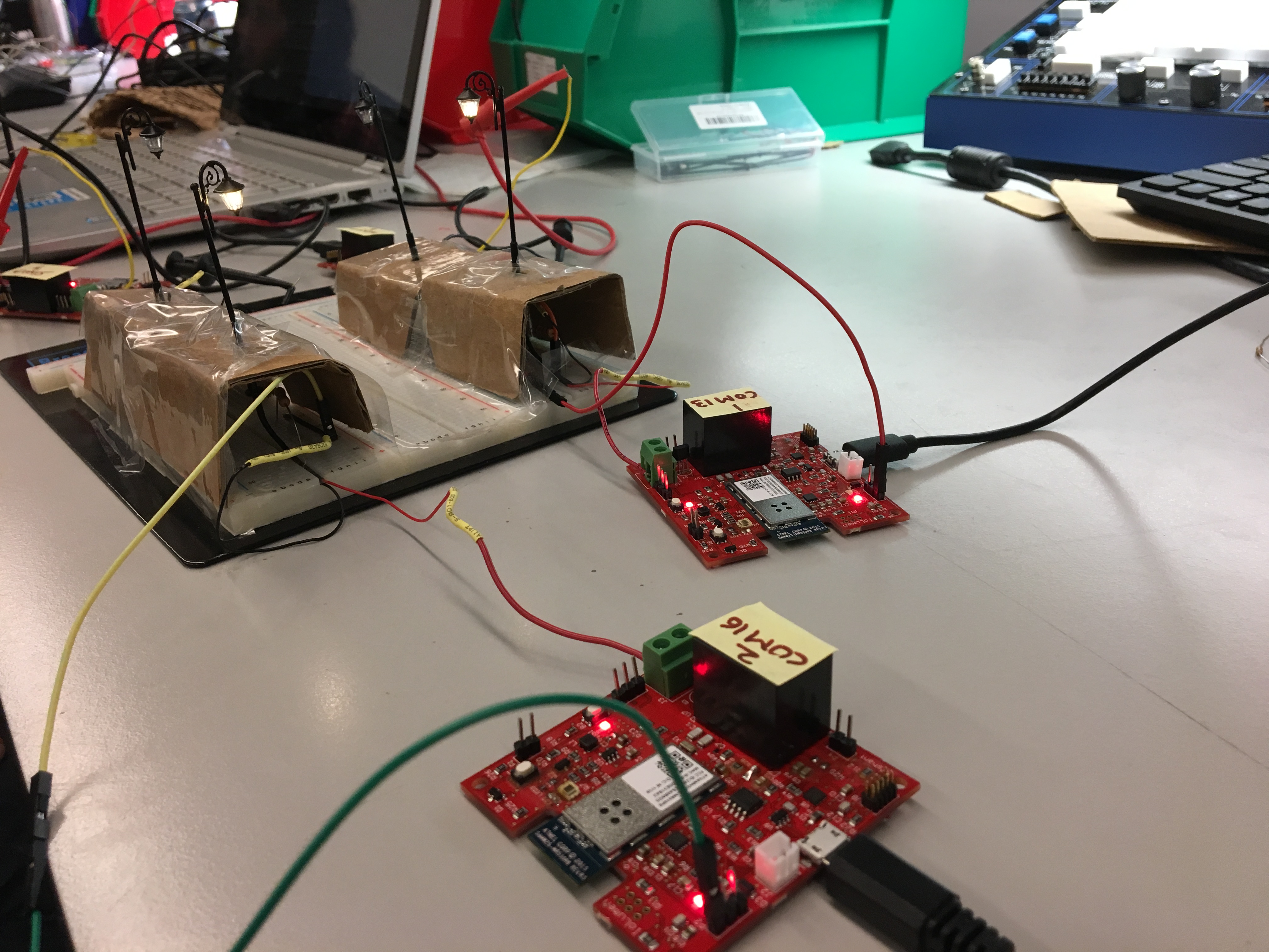
Demo Setup
-
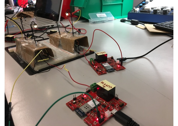
Connecting 4 boards together!
-
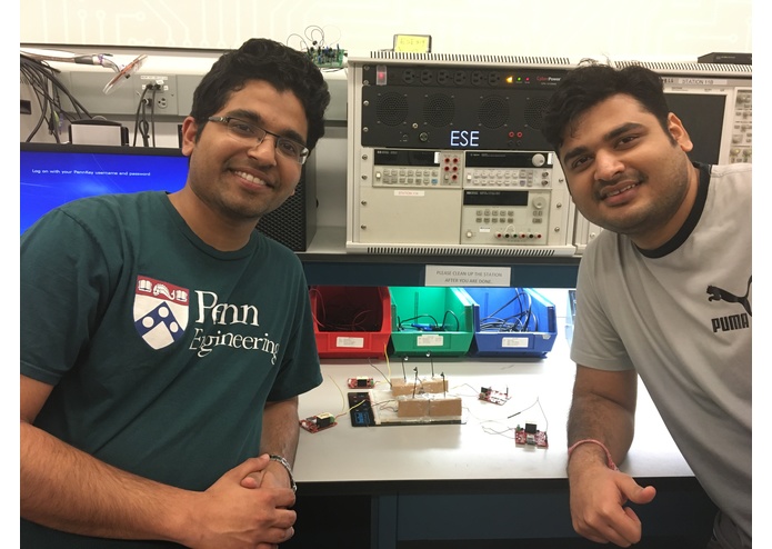
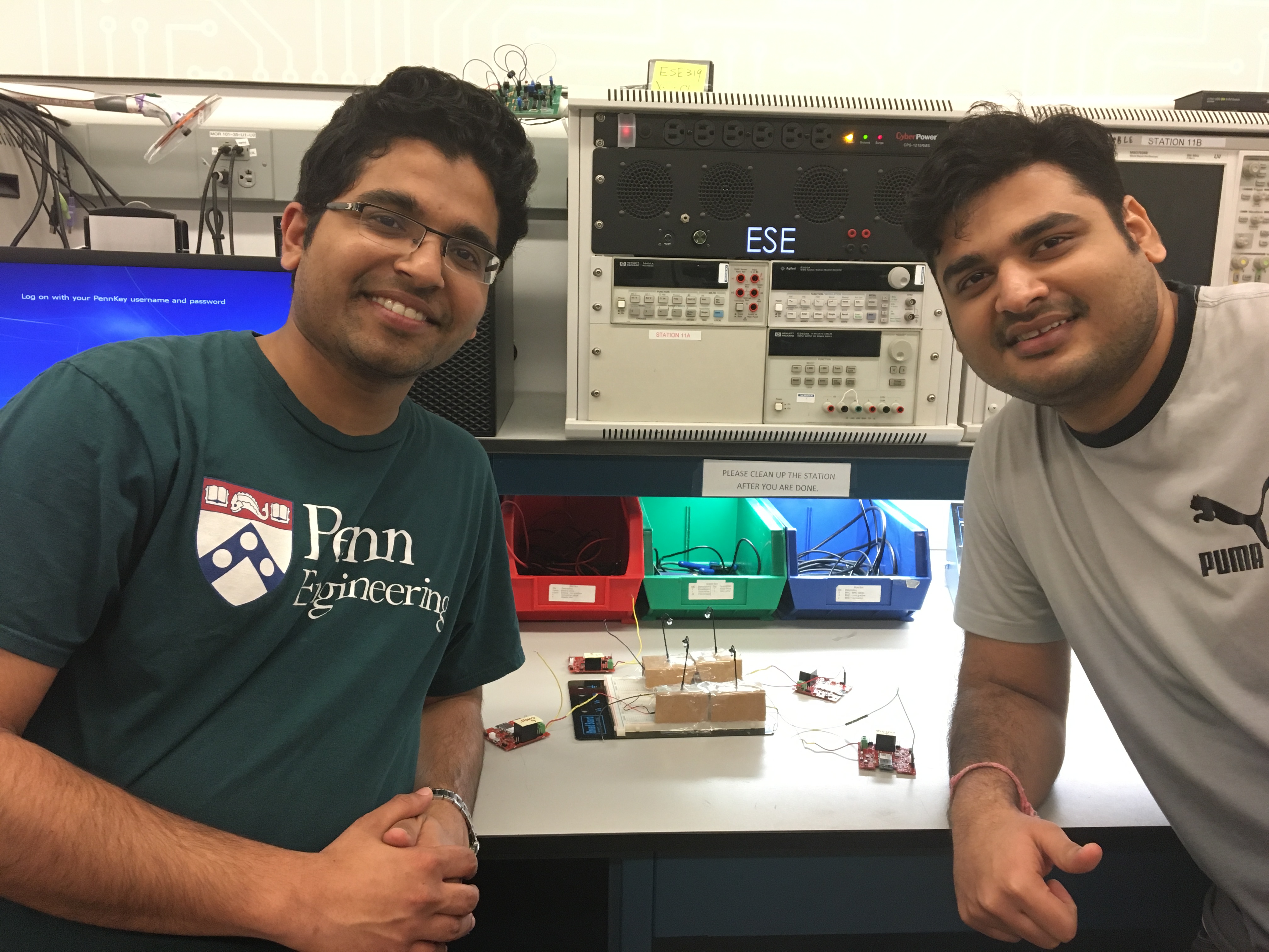
Creators of this project!
-
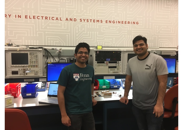
Team- IoLumen

Inspiration
When we search Google maps, it gives you the fastest way to reach your destination. But what if the route given by Google Map is not safe enough for travel during night times. What if the street lamp fuses out and it hasn't come to the notice of civic authorities? What if the light intensity varies in different regions depending on where these street lamps are installed. Will it be possible to control each street lamp individually? Will it be possible to monitor their energy consumption and find out the peak demand throughout the year? We thought of developing a Smart Street Lighting solution IoLumen that could autonomously operate on its own and also bring features of being controlled remotely (if needed) and could monitor the lux levels in the area while also ensuring reduction in the breakdown time to repair these Street lamps. We thought of building a smart street light solution that could effectively tackle all the above problems and bring a safer neighbourhood! 1/10th the Size, Smarter Tomorrow!
What it does
- It is a Smart Street Lighting Solution that monitors the energy consumption of the street lamp based on the on/off time of our Electromagnetic Relay.
- It enables automatic Street light control based on the lux levels read from the light sensor.
- It helps reduce the breakdown time of repairing faulty street lamps by alerting civic authorities
- It trigger the safety hazard lights on the road to alert road drivers and other people when the maintenance personnel tries to repair the high voltage street lamps
How we built it
This project revolved right from the ideation phase to the actual product development for Smart Lighting IoT application. It uses a low power ATSAMSAMW25 wireless module, which has SAMD21 ARM Cortex-M0 microcontroller from Atmel combined with a 2.4GHz ATWINC1500 WiFi chip. It uses a TSL2561 Ambient light sensor that supports fast mode I2C protocol at 400kbps data transfer and an electromagnetic relay that acts as an actuator to turn ON/OFF the street lamp either remotely or autonomously based on the light intensity levels of the area where it is installed. It also supports Over the Air Firmware Updates(OTAFU) by periodically checking for any updates once in 24 hours and downloading the metafile into the external flash and checking for updates by comparing the CRC32 of the existing and new downloaded metafile. The external flash has a golden bootloader image within it that remains untouched so that it can be loaded into the NVM if the bootloader data gets corrupted while downloading or if there is any power disruptions during download session. This project used 0805 size components predominantly and the total component cost was approx $45( excluding the battery cost). It is also very compact ( 60mm X 60mm) in size. We designed the schematic and the layout in Altium tool and generated the NC Drill and Gerber files for PCB manufacturing. The PCB was given for manufacturing and assembling the SMD components to a third party vendor, PCBng while we wrote our own customized bootloader for this product.
Challenges we ran into
One of the biggest challenge was getting our boards fabricated in time. We received our boards after a month and we had only a week for board bring-up before the demo day. We interpreted our relay coil pins wrong and hence our relay was not able to be triggered. To rectify this problem, we had to cut few traces on our PCB and add few external jumper wires for correction. Another challenge that we ran into was that the BJT was not acting like a switch due to improper resistors chosen in the design. We had to modify our schematic design and use MOSFET instead for switching our Electro-mechanical relay. The reset line had very large RC rise time due to which the board was not getting detected. This could be due to extra parasitic capacitance introduced due to long PCB trace. We had to remove the capacitor from the reset line to reduce the RC time after which the board started getting detected by the PC. We had issues with the clock cycles and fuse bits settings in our code while integrating our bootloader and App code together and transferring it from Xplained pro Evaluation board to our actual PCB board.
Accomplishments that we're proud of
- Our compact hardware design which consumes less power and uses MQTT protocol for sending data to the cloud
- Over the Air Firmware Updates of all boards with a single click of a button
- Inter-board communication when put in maintenance board
- Cloud Platform that is user-friendly and reliable
What we learned
We learned the importance of looking into the finer details within datasheets while designing the hardware circuit. Also it is very necessary to follow-up with your PCB vendor even after submitting all the required files. And it is always a wise option to create a backup for all your code throughout the development of the project.
What's next for IoLumen: Smart Street Lighting
We would probably use a light dimmer circuit on our PCB using Diac-Triac mechanism if our budget is increased. Our next goal will be to find out the street lamps that are in maintenance and create a safe route map for travelling during night by integrating with Google Maps API. Another aspect that we would probably look into is create a trend analysis on energy consumption and find out ways on improving the life and efficiency of street lamps based on the data available on cloud.
Built With
- altium
- embedded-c
- node.js
- relay
- samw25
- tsl2561

Log in or sign up for Devpost to join the conversation.