Long-range, low-power wireless communication is a key requirement for many IoT and automation projects. Technologies like Wi-Fi and Bluetooth work well for short distances but consume significant power and are not suitable for remote or battery-powered deployments. LoRa (Long Range) technology solves this problem by enabling data transmission over several kilometers while consuming very little power.
In this project, we interface the Reyax RYLR999 LoRa module with an Arduino UNO to create a simple point-to-point wireless communication system using UART and AT commands.
Why Use LoRa?
LoRa is designed for applications that need:
- Very long communication range
- Extremely low power consumption
- Small, infrequent data packets
It uses Chirp Spread Spectrum (CSS) modulation, which allows the receiver to detect very weak signals even in noisy environments. LoRa typically operates in license-free ISM bands such as 433 MHz, 868 MHz, and 915 MHz, making it ideal for IoT sensors, alerts, control systems, and remote monitoring.
Reyax RYLR999 Module Overview
The RYLR999 Lite is a compact wireless module that combines:
- LoRa (868/915 MHz) for long-range communication
- Bluetooth Low Energy (2.4 GHz) for short-range communication
The module provides separate UART interfaces for LoRa and BLE, allowing independent control of both radios. Configuration is done using simple AT commands, making it beginner-friendly while still powerful enough for real-world applications.
One unique feature of the RYLR999 is that it can act as a BLE-to-LoRa bridge, enabling data from a smartphone to be forwarded over long distances using LoRa.
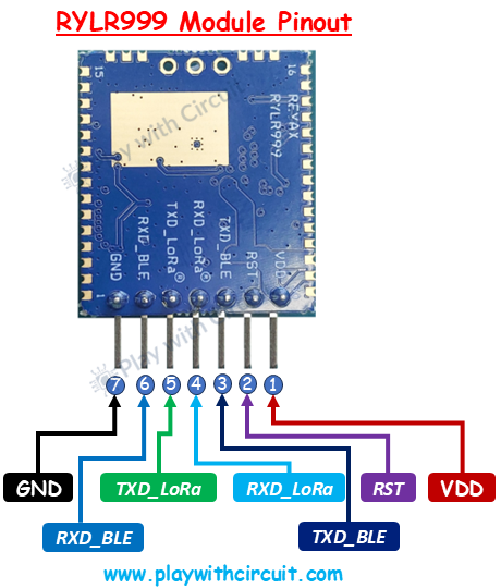
RYLR999 Pinout
Below are the LoRa-related pins used in this project, explained from a hardware perspective:
VDD: This is the power input pin for the module. It requires a regulated 5V supply. Always ensure a stable voltage source to avoid communication issues.
GND: Common ground reference. This pin must be connected to the ground of the Arduino and all other peripherals.
RXD_LoRa: This pin receives data and AT commands for the LoRa subsystem. Commands sent from the Arduino enter the module through this pin. It operates at 3.3V logic level, which is why a voltage level shifter is required.
TXD_LoRa: This pin transmits LoRa data and AT command responses back to the Arduino. Any received LoRa packet is output through this pin.
RST: Active-low reset pin. Pulling this pin LOW resets the module. It is optional in basic setups but useful for recovery and debugging.
Hardware Required
- Two Arduino UNO boards
- Two Reyax RYLR999 LoRa modules
- One bi-directional voltage level shifter (5V ↔ 3.3V)
- One 16×2 I2C LCD (used only on the initiator side)
- Jumper wires
- USB cable for programming Arduino
- External power adapter
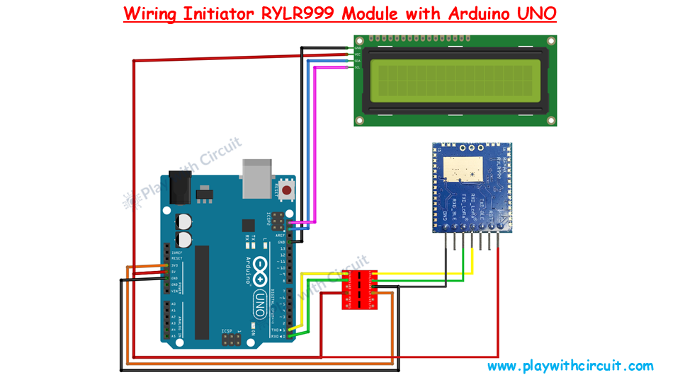
Wiring the RYLR999 with Arduino (Initiator Side)
Since the Arduino UNO uses 5V logic and the RYLR999 uses 3.3V UART logic, a voltage level shifter is mandatory to protect the module.
Power Connections
- Arduino 5V → RYLR999 VDD
- Arduino GND → RYLR999 GND
UART Connections (Through Voltage Level Shifter)
- RYLR999 TXD_LoRa → Arduino RX (via level shifter)
- Arduino TX → RYLR999 RXD_LoRa (via level shifter)
To power the voltage shifter correctly:
- Arduino 5V → HV pin
- Arduino 3.3V → LV pin
These power connections are essential for proper bi-directional voltage translation.
I2C LCD Connections (Initiator Only)
- LCD VCC → 5V
- LCD GND → GND
- LCD SDA → A4
- LCD SCL → A5
Ensure that the I2C address jumpers (A0, A1, A2) on the LCD module are not shorted when using address 0x27, as referenced in the code.
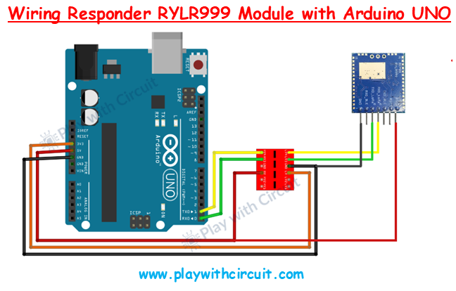
Wiring the Responder Node
The responder setup is simpler:
- Same power connections
- Same UART wiring with voltage level shifter
- No LCD required
This Arduino continuously listens for LoRa messages and responds automatically when data is received.
for Full Tutorial & Code read the complete article at Play with Circuit.

Log in or sign up for Devpost to join the conversation.