-
Connect BMP280 Pressure Sensor Module With Arduino

Inspiration
If you want to build your own temperature monitoring system or measure the altitude of a drone, or just want to measure the atmospheric pressure in your area, then one of the best modules to use in your project is the BMP280 Pressure Sensor Module. BMP280 is an absolute pressure and temperature monitoring sensor, which is an upgraded version of BMP085, BMP180 and BMP183 sensors. Why is it called an upgraded version? It will be discussed in the following sections.
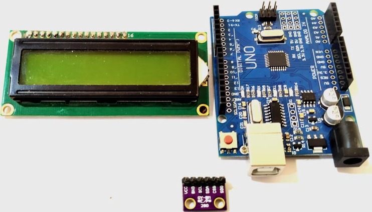
The BMP280 sensor module can be used with microcontrollers such as Arduino, PIC, AVR, etc. For this project we will use Arduino Uno and BMP280 along with LCD 16x2 display module to display temperature and pressure values. Before connecting the BMP280 with Arduino, we need to download the BMP280 Arduino library developed by Adafruit.
Supplies
Arduino BMP280 Connect wires Breadboard LCD monitor - 16x2
How I built it
The BMP280 sensor module operates at a minimum voltage (VDD) of 1.71V, whereas previous versions of the sensor module operated at 1.8V (VDD). In terms of current consumption, the BMP280 consumes 2.7uA, while the BMP180 consumes 12uA, and the BMP183 and BMP085 consume 5uA each. The BMP280 also supports new filtering modes. The BMP280 sensor module supports I2c and SPI protocols, while the remaining sensors support I2c or SPI. The BMP280 sensor module has an accuracy of ±0.12 hPa, which corresponds to an altitude difference of ±1 m. Due to these key properties, it is mainly used in various applications.
The BMP sensor consists of a pressure sensing element, a humidity sensing element and a temperature sensing element, which are further connected to the pressure front end, humidity front end and temperature front end. These front-end ICs are sensitive analog amplifiers used to amplify small signals. The output of this analog front-end IC is fed as an input signal to the ADC. In this case, the analog value is converted into a digital voltage and this voltage is fed to the logic circuit for further connection with the outside world.
The BMP280 sensor module consists of three power consumption modes, sleep mode, forced mode and normal mode. In sleep mode, no measurements are performed and power consumption is minimal. In forced mode, a single measurement is performed based on the selected measurement and filtering options. Normal mode continuously cycles between measurement and standby periods, the period of which will be defined by Tstandby. The current in standby mode is slightly higher than in sleep mode.
Circuit Diagram Connecting BMP280 to Arduino
The circuit diagram for connecting Arduino with BMP280 sensor and LCD is shown below.
The VCC and GND pins of the sensor are connected to the 3v3 and GND pins of the Arduino. The SCL and SDA pins of the sensor are connected to A5 and A4 of the Arduino board.
Arduino Program to Connect BMP280 With Arduino
These libraries are included to enable special functionality. #include header file We can directly read the values from the sensor. The #include header facilitates communication using I2C. The #include header file is used to access special functions of the LCD, such as lcd.print(), Lcd.setCursor(), etc. These header files can be downloaded using the link given above. The downloaded file will be in zip format. Now open Arduino and select Sketch>include library>Add.zip library. Now add the downloaded file.

Log in or sign up for Devpost to join the conversation.