Inspiration
We all watched the recent progress on NASA's Artemis mission, and upcoming plans to establish permanent bases on the Moon and even Mars. At such an exciting and revolutionary time in the history of space exploration, an important and often overlooked necessity for civilization beyond our planet is means of transportation of people and goods. Extraterrestrial rovers have been around for many decades, and have always used passive suspension mechanisms, notably the Rocker-Bogie suspension. The disadvantage of this mechanism, despite its simplicity, is that it is unable to keep the body of the rover level across uneven terrain. This limits the speed the rover can drive at (exacerbated by the low-gravity of extraterrestrial planets) and can cause noise in sensor data. NASA originally used this technology because it was reliable and extra compute hardware was not accessible. With the exponential improvement in semiconductors, cheap and reliable embedded computers are ubiquitous and can be used for more advanced suspension systems. We wanted to prove this concept with a desktop-sized rover which can dynamically adjust wheel heights to keep the body level at all times. NASA is researching similar technologies for the VIPER rover which is set to go to the moon soon.
What it does
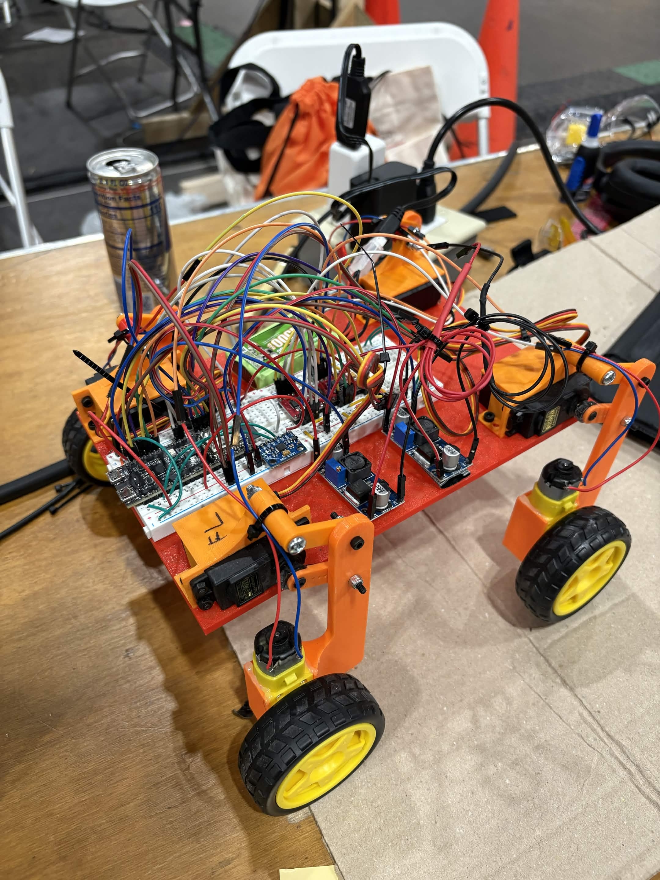
4 servos (one per wheel) drive a 4 bar linkage which connects the arm that the motor and wheel sit on. The 4 bar linkage lifts the arm up and down, allowing the servo to directly control the height of its respective wheel. An ESP32 connected to an MPU6050 IMU monitors the roll and pitch of the robot continuously, and issues corrections to the servos in real time to restore the balance of the robot.
A webapp is used to control the rover wirelessly and tune the control parameters. The webapp also provides meaningful telemetry metrics and visualization.
How we built it
The body and components are all 3D printed. An ESP32 microcontroller connected to 2 TB6612 motor drivers which power DC motors that drive the wheels. 4 MG995 servos power the 4 bar linkage and change the height of the wheels. The system is powered by a 7.4V LiPO battery which are connected to Buckdown converters which lower the voltage to 5V for digital circuits.
Challenges we ran into
We had two designs originally and manufactured both. We put one together - then the other. The first design used a rack and pinion to directly move the wheels up and down. The second used a 4 bar linkage to achieve a similar result. We were able to assemble and test both. The first was simple to program because it went straight up and down, while the second was lighter and had more space for electronics. In the end we went with the latter.
The 6-Dof IMU did not output absolute roll and pitch directly. To calculate it, we performed trigonometry to isolate roll and pitch and fused the gyro and accelerometer outputs through a complementary filter.
We originally tried to implement a PID controller to perform real time leveling. Despite hours of tuning both rover designs, we could not get a tune that eliminated steady-state error and didn't jitter. We then realized that the nonlinear behavior of the 4 bar linkage mechanism resulted in the PID outputs not being directly reflected in the output. We then made a lookup table, listing different angular displacements and their corresponding height displacement from the neutral position - we linearly interpolated between data points. With this, we found the linkage was non-monotonic. The height would increase and decrease so the same height could come from multiple angles. We tried to pick a linear segment but this limited the range too much. In the end, we settled on a simpler controller which simply computed an error term and used it to directly calculate servo commands to reverse it, which has worked okay so far. We believe with more time and expertise, a better control system could produce even smoother results.
Accomplishments that we're proud of
All of our first times using ESP32 First time designing 4 bar linkage First time using many of these parts Assembling and debugging complicated wiring Iterating over multiple designs for mechanism and control system Developing a clean user interface for our product with webapp
What we learned
4-bar linkages are nonlinear. We found it was hard to model their behavior mathematically to use in our control system (especially when sleep deprived and hallucinating). Our control system was further challenged because of the lack of feedback - the only input we had was IMU with no feedback from the servos or anything else.
What's next for Horizon
There are still possible improvements on the control system. This will probably turn into a free time project - if we have time we would love to revisit and make it smoother.
And definitely, we will be watching the upcoming achievements in space exploration - undoubtedly bound to be some of the most significant human accomplishments of all time. We would love to see rovers with active suspension like ours assisting in that mission.


Log in or sign up for Devpost to join the conversation.