-
-
Unarmed
-

Armed
-
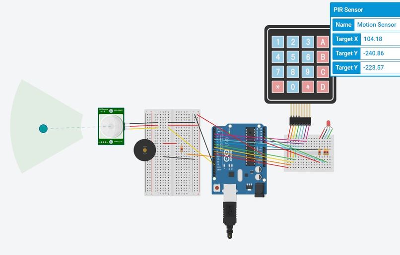
Motion Detected
-
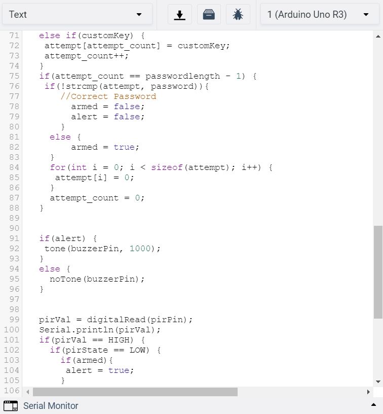
Code3
-
Code1
-
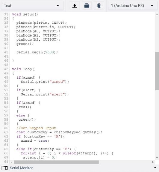
Code2
-
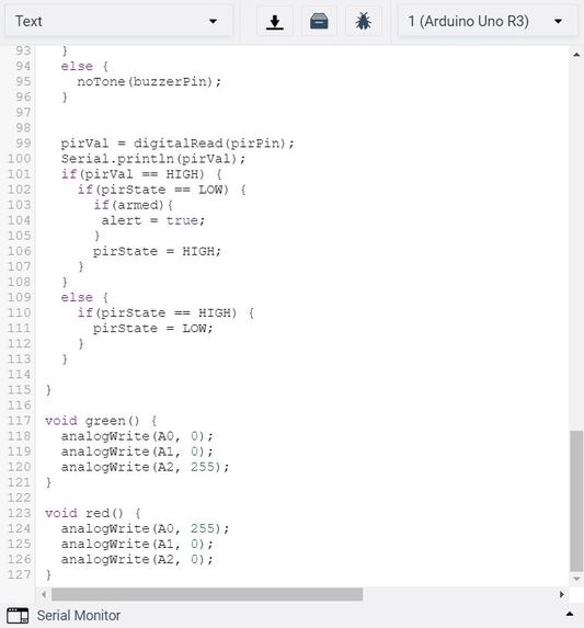
Code4


What is your idea?
Our idea was to build a home security alarm utilizing the sensors and actuators compatible with Arduino, including those we had encountered in lab and lecture. With the goal of increasing home security, consistency was our key focus. We wanted to build something that worked reliably every time.
What was the process like building your product?
We started with a discussion of what the key aspects of a home security alarm should be, and when it would be in motion. We identified that home intruders and unwanted movement in or in front of a house would be our primary focus. After identifying the need for movement detection, we decided to use a PIR sensor to sense motion. Our second goal was to allow the user to easily and securely be able to arm and disarm the alarm with a password. If the alarm went off when someone entered their own house, they could turn it off utilizing the keypad and a previously set alarm. If a home intruder came in, they would be unable to turn the alarm off. Lastly, we decided to use a Piezo in order to make the alarm sound. This would alert the homeowner to any unwanted movement, and in a real-world situation would need to be loud enough to wake the homeowner from sleep. Once we determined these requirements, we added the necessary components into our TinkerCAD project and wired them up properly, and wrote the Arduino code necessary to create our desired functionality.
Explanation of the hardware/software
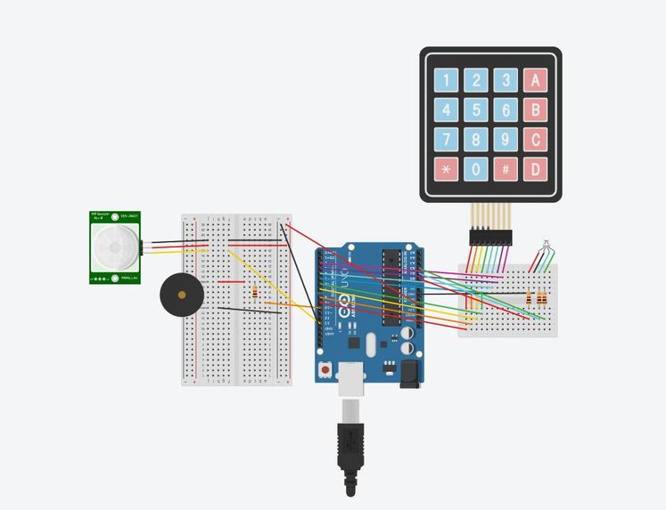
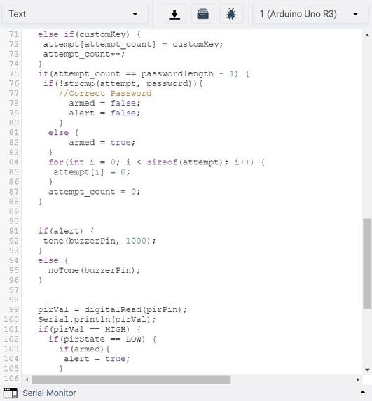
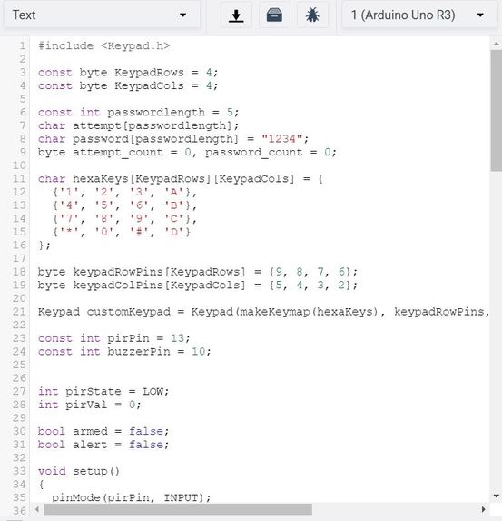
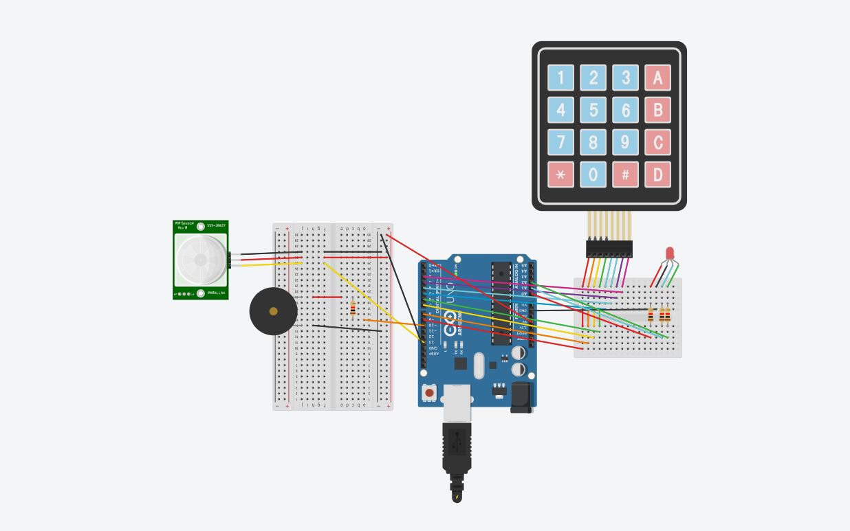
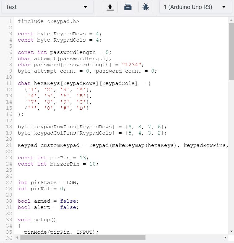
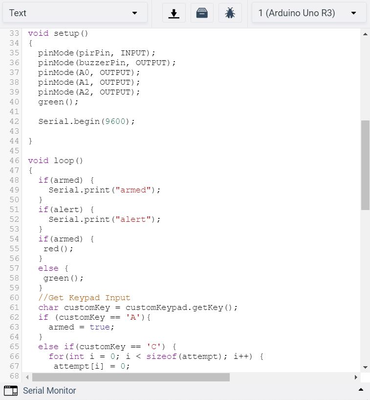
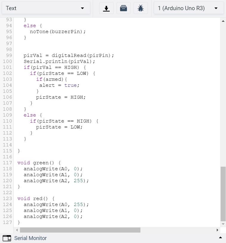
The hardware consists of one Arduino connected to two breadboards. One of the breadboards is connected to an LED RGB (three resistors) and the keypad. The other breadboard is connected to the PIR motion sensor and the Piezo. The Piezo and LED RGB are actuators. Pressing A arms the home security alarm. When armed, the LED RGB will turn red. If the motion sensor is moved, the (loud and ear piercing) alarm will go off. In order to turn the alarm off one has to press C, then enter the password. The reason that the piezo is hosted on on the breadboard, whereas the other components merely use the breadboards as an intermediary is that, in the physical version of the project, you would want long wires connected to both the keypad and led, and the motion sensor, as these would each be in separate housings and in most use cases would be separated from each other by some distance, for example, the PIR sensor looking at the door from the outside, and the keypad on the wall inside. The Piezo would be in the main housing with the Arduino. The software uses the Keypad.h library to deal with keypad input, it uses a 2d array of the key values to convert pin input to the key value. If the key value is A then it arms the alarm, and if the password is ever entered it disarms and turns off the alert if it has gone off. In order to make password entry more convenient if C is pressed is clears the current attempt at password entry (it is hard to tell what digit of input you are at if you mess up the password entry). There is a boolean value alert which is set to true if armed and the PIR state goes from low to high, meaning movement. When it is true the buzzer goes off, otherwise, the buzzer emmits no tone. The led is changed to green when armed is false, and red when armed is true. There are two helper methods, green() and red() to perform this function.
What would you add if you could have built this in person (sensors, hardware, 3D printing/laser cutting etc.)?
It would have been very exciting to do an actual hardware implementation of our project. One consideration would have been designing an alarm box that was inconspicuous, possibly building 3D printed boxes, one that would house the Arduino and breadboards, and potentially also the keypad and led and another that would house the PIR sensor. One of the difficulties we ran into was calibrating a distance sensor that would detect the when a door opens we intended for this to be a second mechanism for alert, but in the TinkerCAD environment it is difficult to deal with and leads to the unintentional setting off of the alarm frequently as the default distance in the simulation is pretty far.
Log in or sign up for Devpost to join the conversation.